VT6L Maintenance 18. Controller Unit
144 VT series Maintenance Manual Rev.2
18.3 Replacing CPU/DPB Board
Maintenance
parts
CPU/DPB Board
Cross-point screwdriver (No. 2)
Board
1)
the power board.
Reference: 18.2 Replacing Power Board
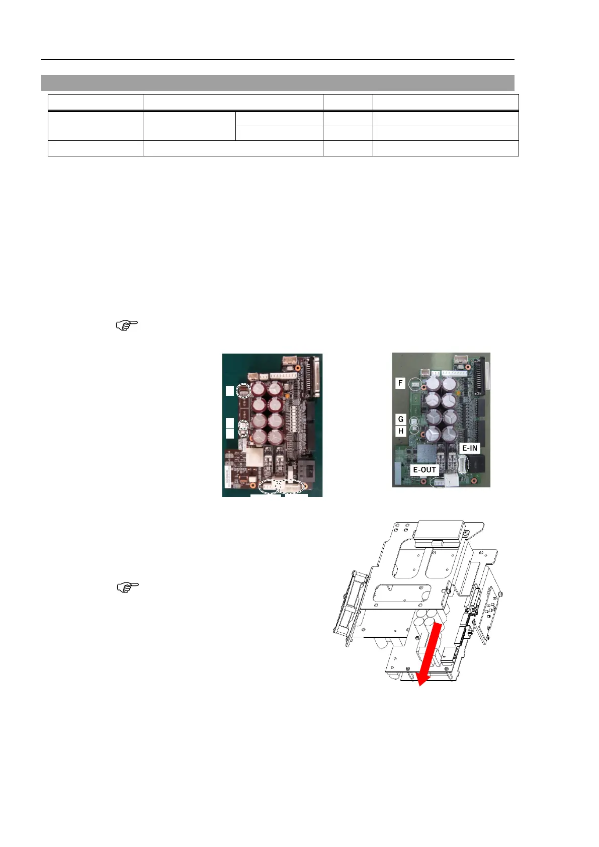
the CPU/DPB board connectors.
E: Power connector (IN/OUT ×1 for each)
F: Cooling fan connector
G: Regenerative resistor connector 1
H: Regenerative resistor connector 2
Remember the cable layout for
reconnecting after replacement.
AC
specification
DC
specification
the CPU/DPB board.
Binding head screws: 5-M3×6
the mounting screws.
CPU/DPB board to the

 Loading...


