VT6L Maintenance 7. Covers
42 VT series Maintenance Manual Rev.2
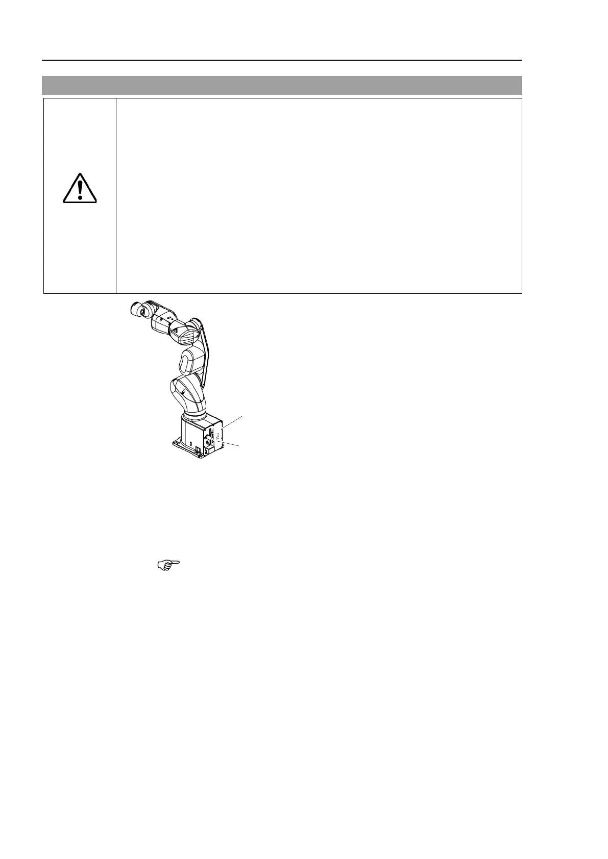
7.7 Connector Plate
CAUTION
■
Do not remove the connector plate
forcibly. Removing the connector plate
forcibly may result in damage to the cables, disconnection, and/or contact failure.
Damaged cables, disconnection, or contact failure is extremely hazardous and
may result in electric shock and/or improper function of the robot system.
installing the connector plate, be careful not to allow the cables to interfere
with the plate mounting and d
o not bend these cables forcibly to push them into
Unnecessary strain on cables may result in damage to the cables, disconnection,
and/o
r contact failure. Damaged cables, disconnection, or contact failure is
extremely hazardous and may result in electric shock and/or improper
function of
routing the cables, observe the cable locations after removing the connector
ate. Be sure to place the cables back to their original locations.
Connector
Plate
Removal
, Cleanroom model:
Remove the Power Cable Cover.
Reference: 7.6 Power Cable Cover.
ower cable clamp and then remove Power Cable Connector.
When removing the Power cable connector, pull it out with pushing clips on
both side of the connector.
Unscrew the Connector Plate mounting bolts and then remove the Connector Plate.
model:
1)
Unscrew the Connector Plate
mounting bolts and then remove the Connector Plate.
emove the base gasket from the base.

 Loading...


