VT6L Maintenance 18. Controller Unit
VT series Maintenance Manual Rev.2 143
18.2 Replacing Power Board
CAUTION
■
part. Be sure to wear protective gloves when removing the
power board or disconnecting cables.
Maintenance
parts
Power Board
DC specifications 1
2207410
(S/N: VT65T02*** only)
2216953 (all DC specification models)
Cross-point screwdriver (No. 2)
ower Board
1)
the Controller Unit.
Reference: 18.1 Replacing Controller Unit
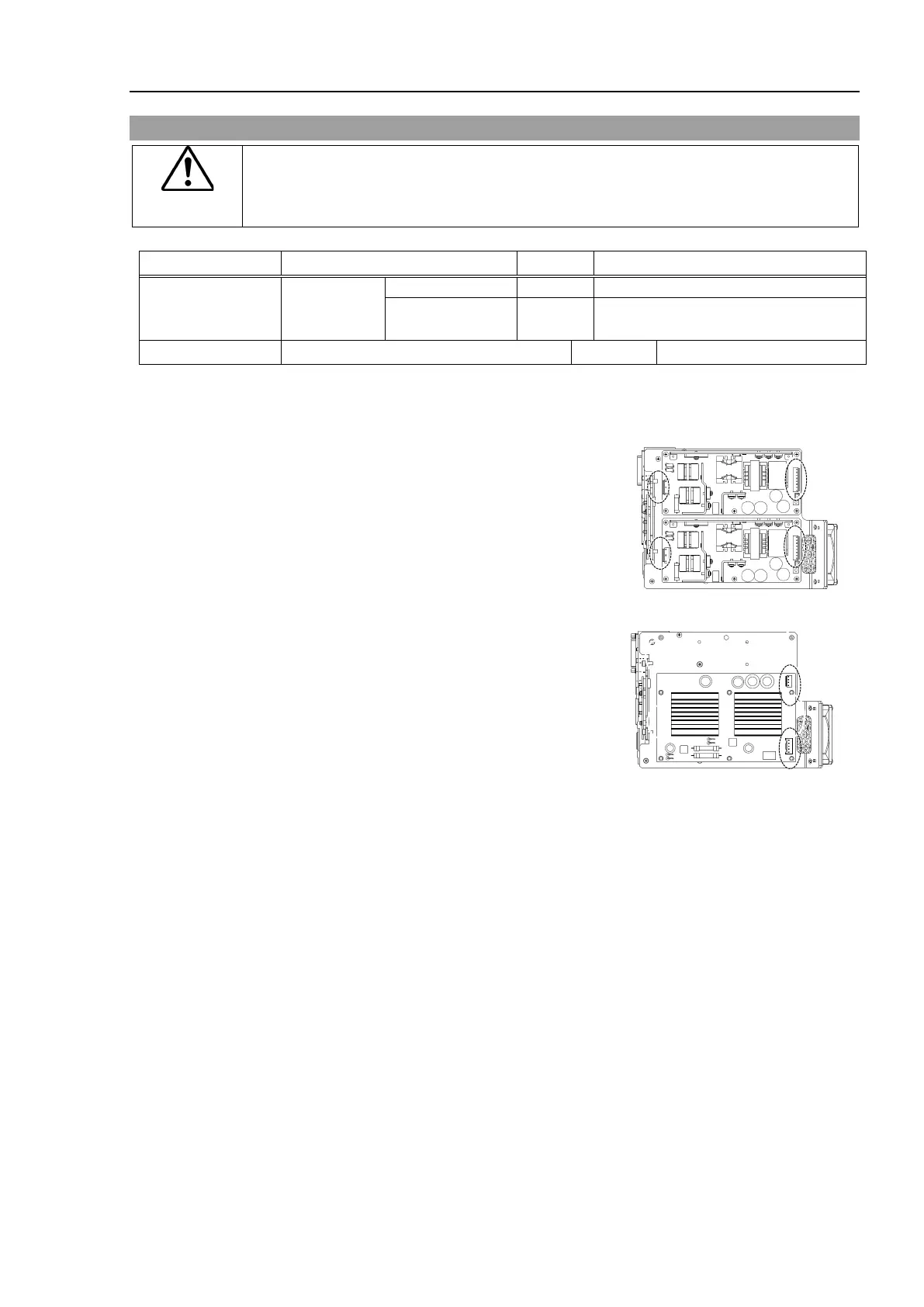
the connectors of the power board.
Power connectors
AC specification: (IN/OUT ×2 for each)
DC specification : (IN/OUT ×1)
the power board.
Pan head screws:
AC specification: 10-M3×8 Sems
DC specification: 6-M3×8 Sems
ower Board
1)
Pan head screws:
AC specification: 10-M3×8 Sems
DC specification: 6-M3×8 Sems
Tightening torque: 0.45 ± 0.1N·m
Connect the connectors of
the power board.
Power connectors:
AC specification: (IN/OUT ×2 for each)
DC specification: (IN/OUT ×1 for each)
3)
ount the Controller Unit.
Reference: 18.1 Replacing Controller Unit

 Loading...


