VT6L Maintenance 18. Controller Unit
VT series Maintenance Manual Rev.2 151
18.7.1 Standard, Cleanroom model
Tool
Cross-point screwdriver (No. 2)
Supplied with the module.
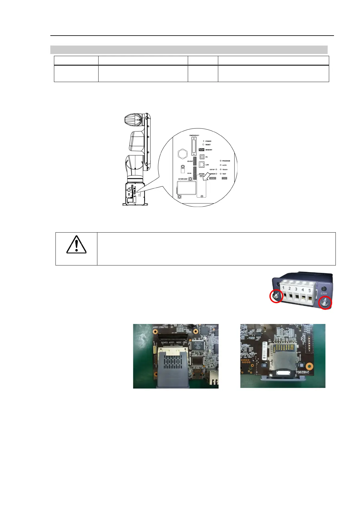
I/O Module
Turn OFF the Manipulator.
Remove the optional slot cover on the back side of the Manipulator.
Standard,
Cleanroom model
Sems bolt: 2-M3×6
Inset the fieldbus I/O module to the optional slot.
CAUTION
Check the tabs of the fieldbus I/O module are
securely hooked on the board when
installing fieldbus I/O module. If tabs do not be hooked securely, connecter or
fieldbus I/O module may get damages.
(4) Tighten screws by using hex lobe wrench until
fieldbus I/O module is fixed completely.
Image of installation
I/O Module
Removal
Standard,
Unscrew the screws by using special tool until fieldbus I/O module is loosened.
Remove the fieldbus I/O module.
You can remove the module by pulling loosened screws toward.
Mount the optional slot cover.

 Loading...


