VT6L Maintenance 8. Cable
VT series Maintenance Manual Rev.2 59
the cables inside the each
Grease: GPL-224
Between Base-Arm #1 : 4.5±1g
Between Arm #1-Arm #2 : 4.5±1g
Between Arm #2-Arm #3 : 2.8±0.5g
Between Arm #3-Arm #4 : 2.8±0.5g
Apply grease evenly to the entire cable inside
the sleeve and the end of the sleeve by
the grease, be careful not to attach the grease to the AMP board.
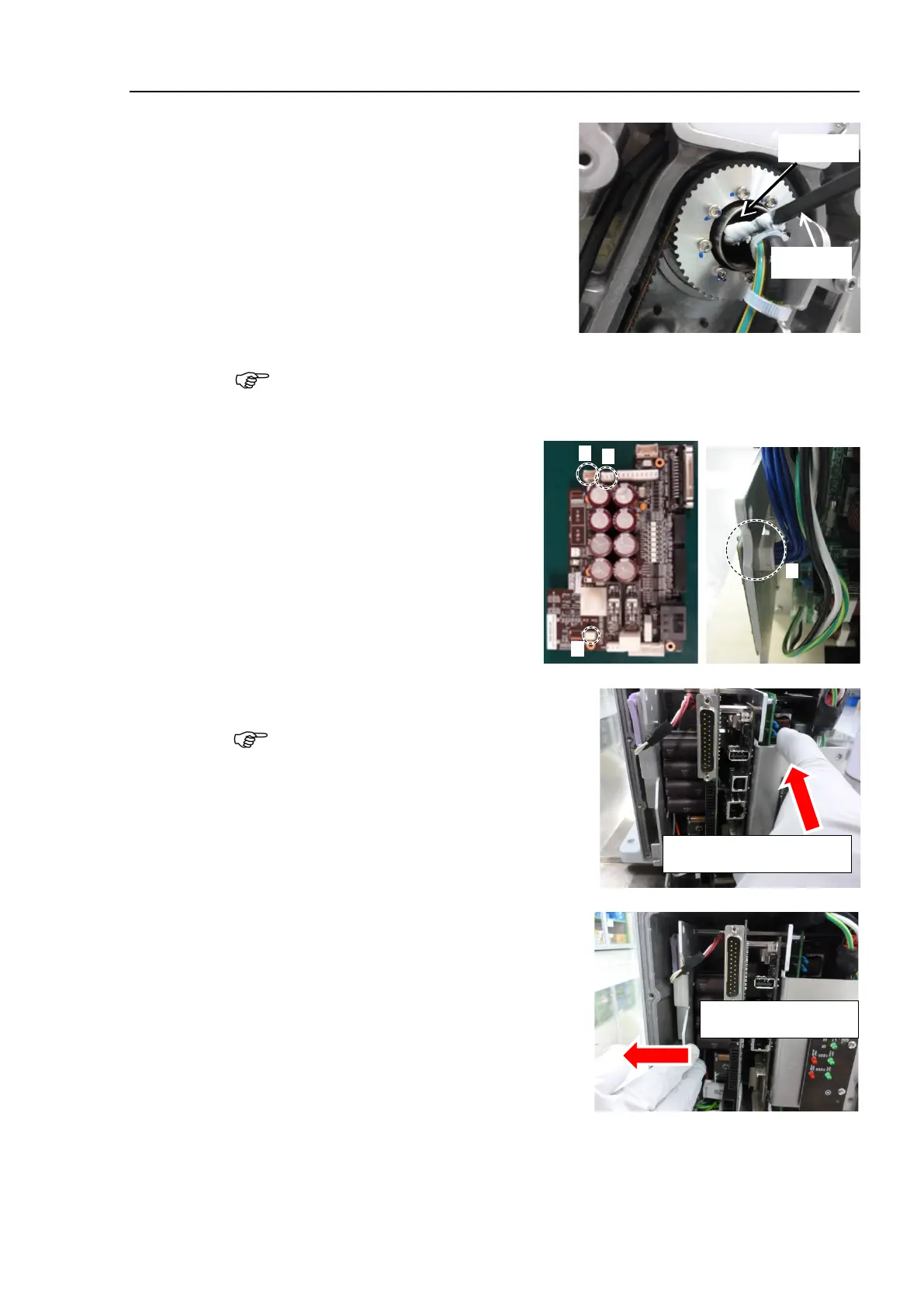
Connect the following connectors to
the Controller
Unit.
A: Power cable connector
B: Signal cable connector
C: LED connectors × 2
the Controller Unit into the base.
Insert the Controller Unit while moving it to
the right (see the
picture).
Then, gently move the plate of the Controller
Unit to
the left and let the thermal conductive
sheet contacts with the wall inside
the base.
Move it to the right to insert

 Loading...


