EG_GenPro25e_1055_UG_002_UK
Descriptions and non-contractual illustrations in this document are given as an indication only.
ERCOGENER reserves the right to make any modification.
Dct_427_02
3 Interfaces
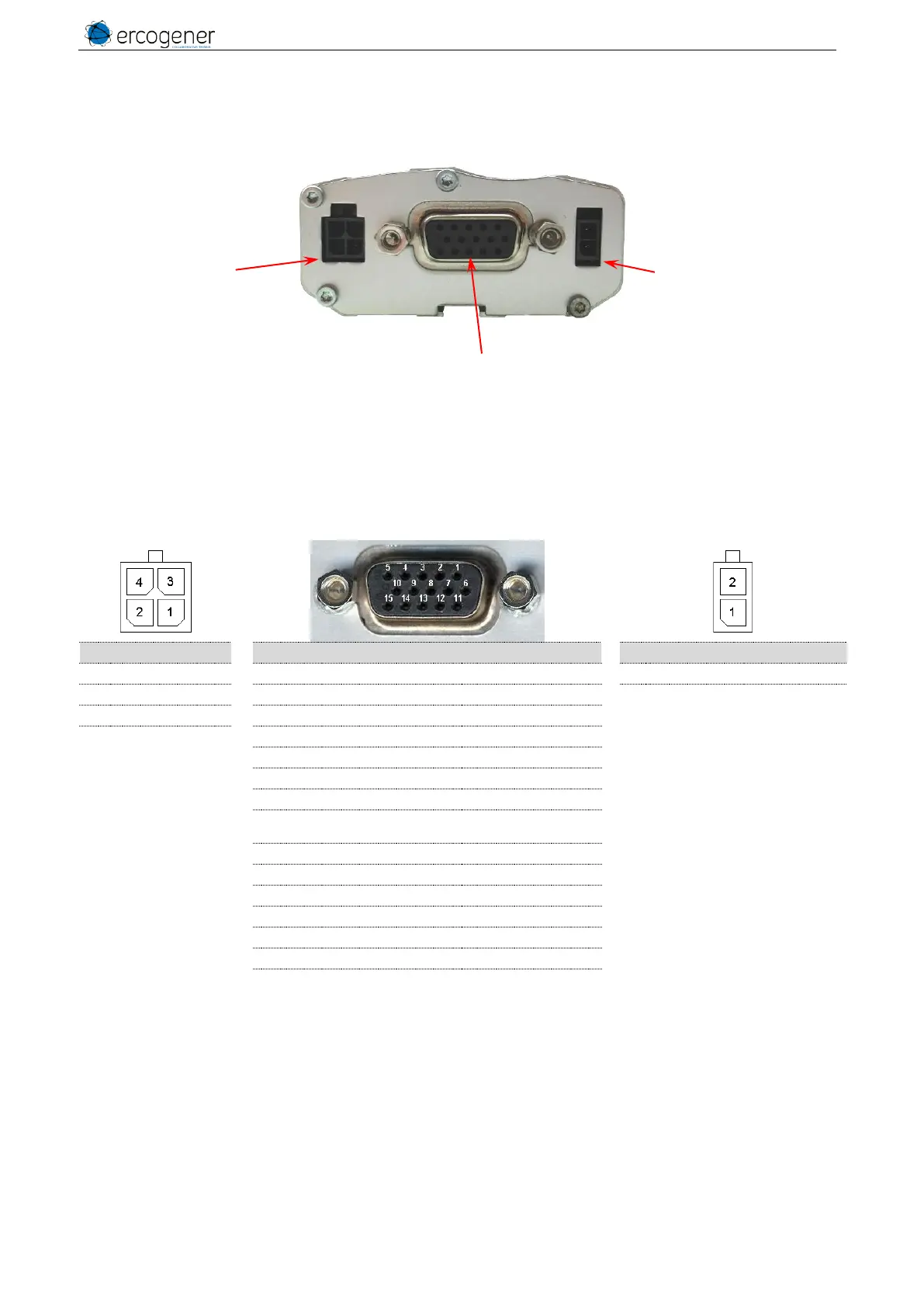
3.1 Front side
Figure 4 : Front side
See ANNEX 1 - 4-pins Micro-FIT cable (Power supply), ANNEX - 2-wire Micro FIT cable connector
(Input/Output), for the wiring of the different connectors.
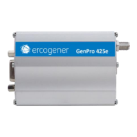
Table 4 : Front side Connector
Connector
Micro-Fit 4pts/M
Connector
Micro-Fit 2pts/M