EasyManua.ls Logo

Ercogener GenPro 25e - 3.7 Serial link RS232 C

Default Icon
58 pages
Print Icon
To Next Page IconTo Next Page
To Previous Page IconTo Previous Page
Loading...
EG_GenPro25e_1055_UG_002_UK
Page 32 / 58
Descriptions and non-contractual illustrations in this document are given as an indication only.
ERCOGENER reserves the right to make any modification.
Dct_427_02
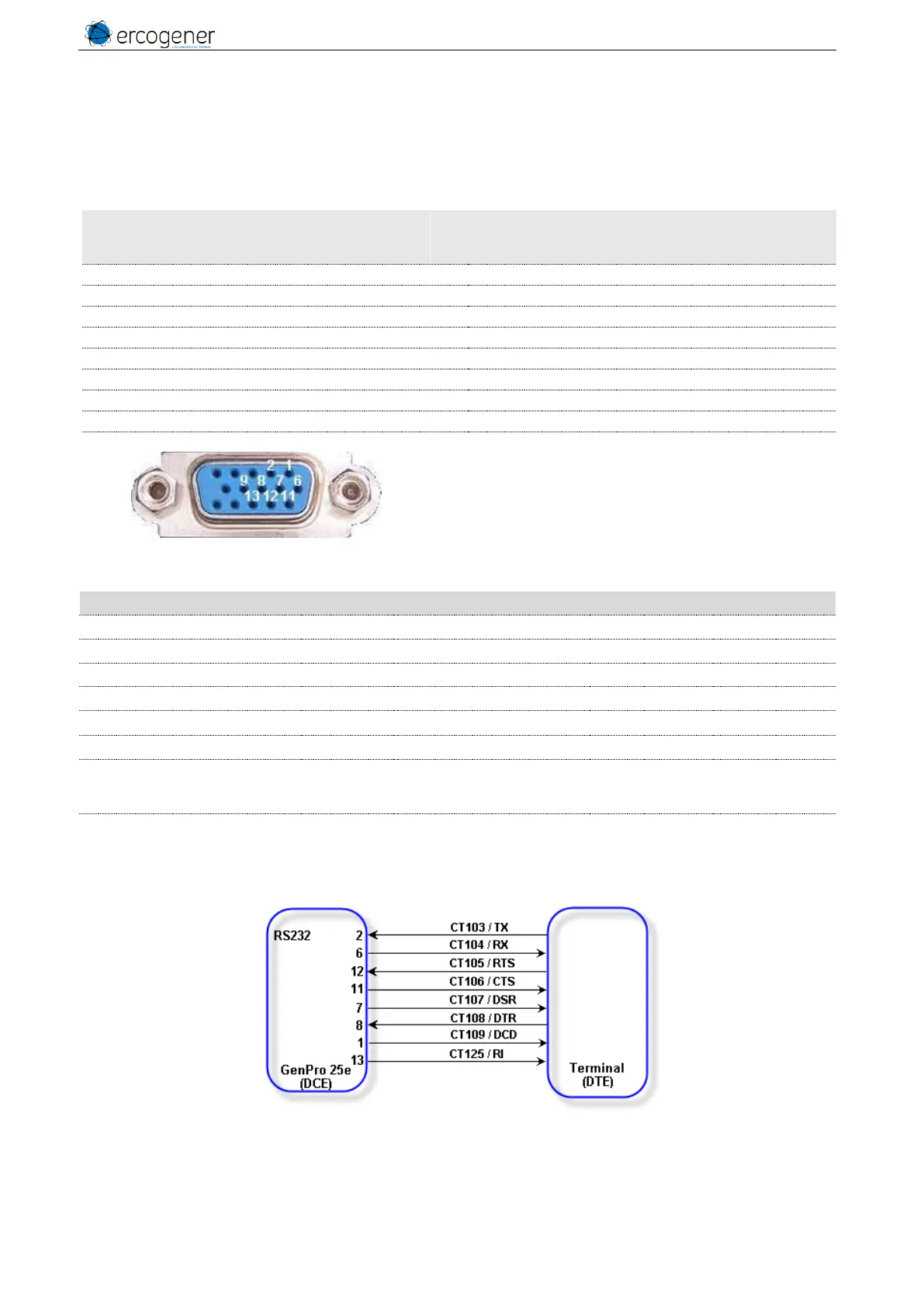
3.7 Serial link RS232C
The RS232 interface makes an adaptation of the voltage levels between the GSM/GPRS module (DCE) and
the communication port of a PC (DTE).
Table 25 : Pins description of RS232C interface
Circuit - V24 - RS232C
Connector
SubD HD 15 points
Pins number
I/O
Description
109 DS DCD
1
O
Data Carrier Detect
103 ED TXD
2
I
Transmit serial data
104 RD RXD
6
O
Receive serial data
107 PDP DSR
7
O
Data Set Ready
108/2 TDP DTR
8
I
Data Terminal Ready
102 TS GND
9
Ground
106 PAE CTS
11
O
Clear To Send
105 DPE RTS
12
I
Request To Send
125 IA RI
13
O
Ring Indicator
Table 26 : Characteristics of RS232C serial link
Characteristics
Symbols
Conditions
Min.
Typ.
Max.
Unit
Input Voltage Range
V
INPUT
Input Voltage Range
-25
+25
V
DC
Input Voltage Low
V
IL
Input Voltage Low
0.4
1.3
V
DC
Input Voltage High
V
IH
Input Voltage High
2
24
V
DC
Input Hysteresis
V
Hys
Input Hysteresis
0.14
V
DC
Input Resistance
R
in
Input Resistance
3
5
7
KΩ
Output Voltage
±5
±6.4
V
DC
Transmitter Output
Resistance
V
OUT
All transmitter outputs
loaded with 3 kΩ to
ground
300
RS-232 Output Short-Circuit
Current
I
CC
±15
±60
mA
Figure 14 : Normalized signals of a RS232C serial link

Table of Contents

Other manuals for Ercogener GenPro 25e

Related product manuals