EG_GenPro25e_1055_UG_002_UK
Descriptions and non-contractual illustrations in this document are given as an indication only.
ERCOGENER reserves the right to make any modification.
Dct_427_02
3.8 BOOT
This signal must NOT be connected, NOT used. The use of the BOOT function is strictly
reserved for the manufacturer and distributors.
Table 29 : Description BOOT input
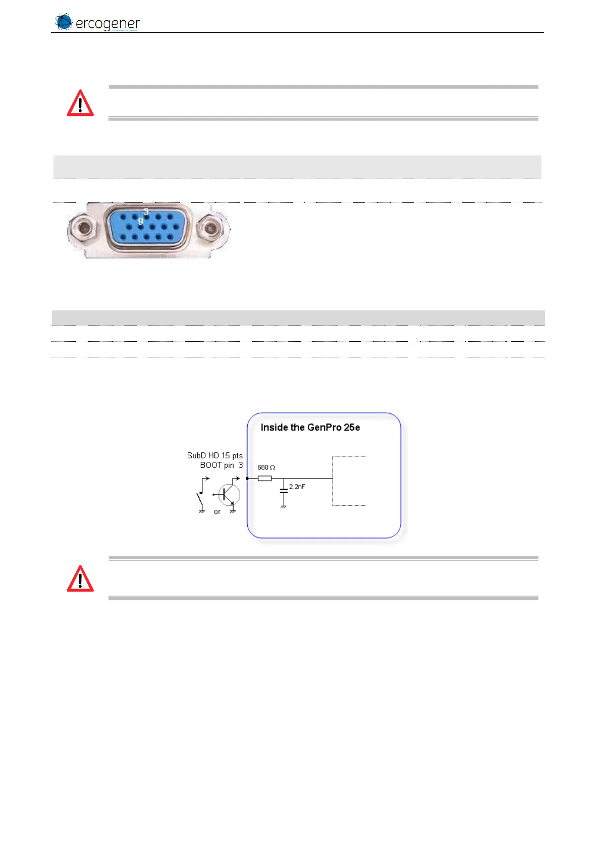
Connector 16 pins
Pins number
Table 30 : Conditions of use of BOOT signal
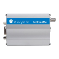
Internal Pull-Up Resistor
Figure 18 : Internal electrical scheme of BOOT
The use of the BOOT signal must be done through a transistor assembly or via dry contact.
The integrator has the responsibility to protect the input from electrical perturbations and to
respect the functioning parameters values.