EasyManua.ls Logo

Ercogener GenPro 25e - Digital Outputs; Figure 13: Internal Electrical Scheme of the Output

Default Icon
58 pages
Print Icon
To Next Page IconTo Next Page
To Previous Page IconTo Previous Page
Loading...
EG_GenPro25e_1055_UG_002_UK
Page 31 / 58
Descriptions and non-contractual illustrations in this document are given as an indication only.
ERCOGENER reserves the right to make any modification.
Dct_427_02
3.6 Digital outputs
Table 23 : Description of digital outputs
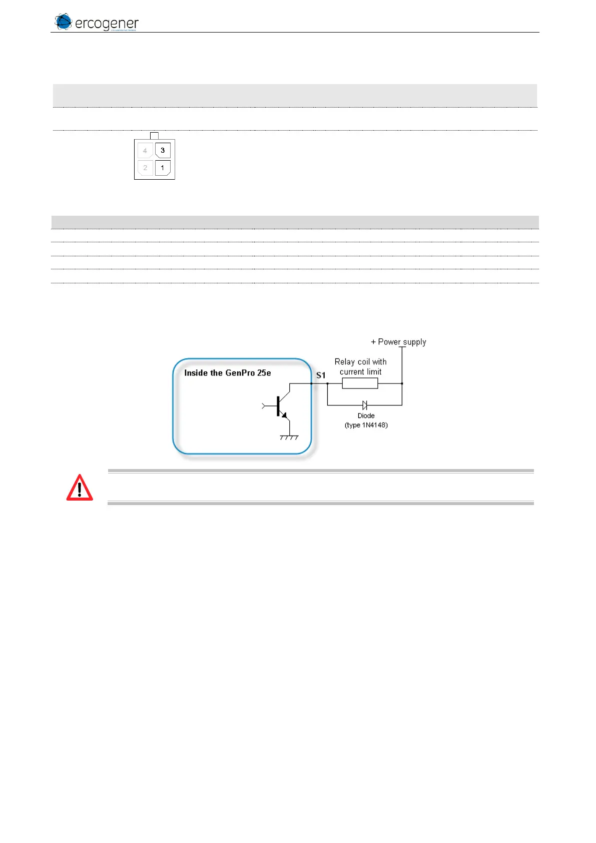
Signal
Connector
Pins number
I/O
Kind of I/O
Description
S1
GND
1 Connector 4 pins
3 Connector 4 pins
S
Logic
Open collector output
Corresponds to wires
Brown for S2
Black for GND
See ANNEX 1 - 4-pins Micro-FIT cable (Power supply)
Table 24 : Characteristics of open collector output
Characteristics
Symbols
Conditions
Min.
Typ.
Max.
Unit
Max. voltage
V
CE0
Transmitter open
48
V
DC
Max. voltage
V
CES
V
BE
= 0 V
48
V
DC
Collector current
I
C
0.5
A
DC
Saturation voltage
V
CEsat
I
C
= 500 mA
1.3
V
DC
Dissipation
P
Ttot
T
amb
≤ 25 °C, T
j
= 110 °C
0.78
W
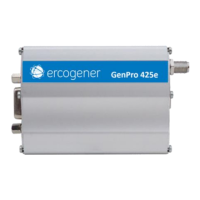
Figure 13 : Internal electrical scheme of the output
No protection is ensured. The user must respect the values of the table below.

Table of Contents

Other manuals for Ercogener GenPro 25e

Related product manuals