EG_GenPro25e_1055_UG_002_UK
Descriptions and non-contractual illustrations in this document are given as an indication only.
ERCOGENER reserves the right to make any modification.
Dct_427_02
3.10 AUDIO
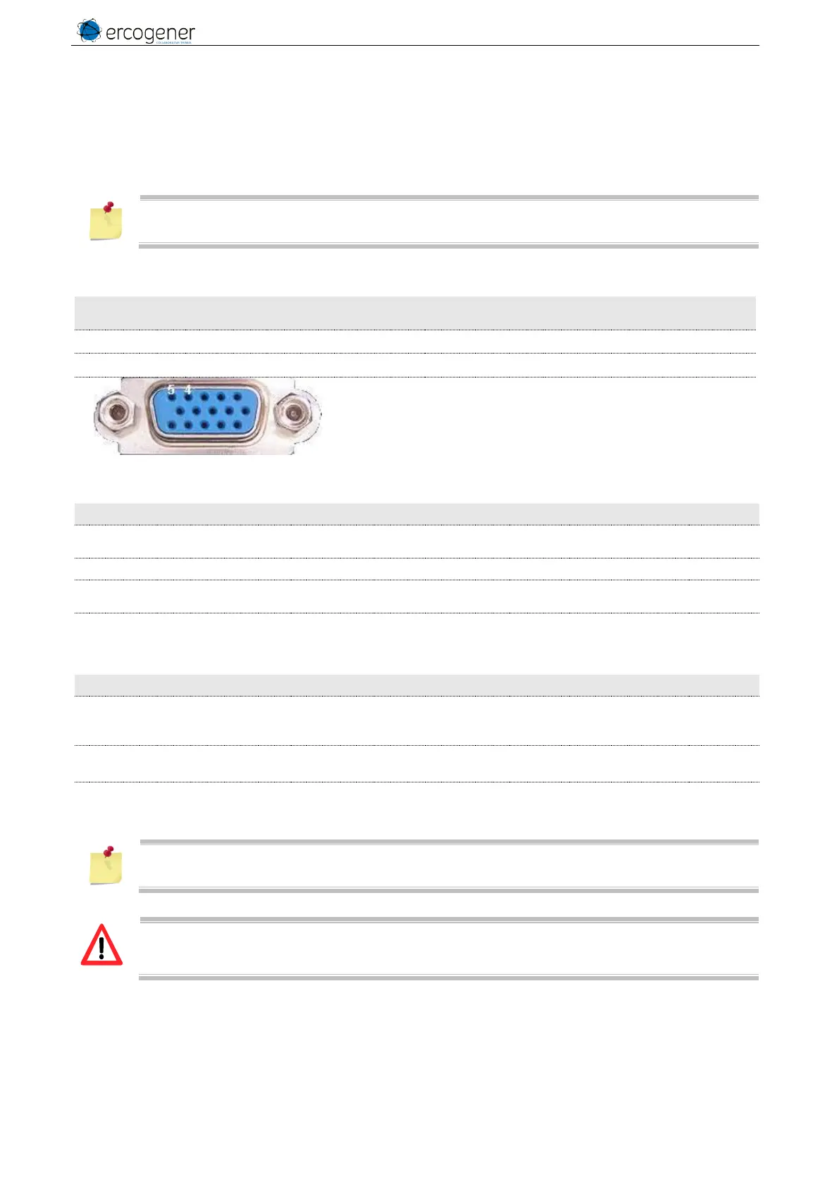
3.10.1 Microphone input (MIC)
The microphone input is designed for a direct connection of the electret condenser of the micro. (For more
details, see the command AT+USPM).
By default, the microphone input is active (pins MICP, MICN).
MICN is internaly connected to the 0V.
Table 33 : Description of Microphone inputs
Connector 16 pins
Pins number
Table 34 : Characteristics of polarization for a dynamic Microphone
Microphone supply open circuit
voltage output
Provided by MIC+ with MIC-.
Microphone supply current
Microphone supply output
resistance
Table 35 : Characteristics recommended for the dynamic Microphone
Maximum Input Level Range
Full scale single-ended voltage.
Signal applied to MICP with
MICN as reference.
Input Impedance –
Mic(+) to Mic(-)
At 1 kHz. Impedance between
MICP and MICN.
Internal discrete high-pass -3dB
cutoff frequency
If the function is not used, the pins 4 et 5 (MIC+, MIC-) must not be connected.
The integrator has the responsibility to protect the inputs from electric disturbances and to
respect the adequate values of the functioning parameters.