EG_GenPro25e_1055_UG_002_UK
Descriptions and non-contractual illustrations in this document are given as an indication only.
ERCOGENER reserves the right to make any modification.
Dct_427_02
3.5.4 Multi ONE-WIRE bus (Option S0485B)
This option Multi ONE-WIRE (S0485B) allows the reading of all 1-wire devices with the possibility to have
several devices on the same bus.
Table 21 : Multi One Wire bus description
Connector 14 pins
Pins number
Corresponds to wires
Blue for Bus Multi ONE-WIRE
Black for GND
see ANNEX 1 - 4-pins Micro-FIT cable (Power supply) et ANNEX - 2-
wire Micro FIT cable connector (Input/Output)
Table 22 : Multi One Wire bus - Electrical characteristics
Output High-level Voltage
Active Pullup On Time
4, 5
Power-On Reset Trip Point
Fall Time High-to-Low
6, 7
Presence-Detect Sample Time
Sampling for Short and Interrupt
4
Active or resistive pullup choice is configurable.
5
Except for t
F1
, all 1-Wire timing specifications and t
APUOT
are derived from the same timing circuit.
Therefore, if one of these parameters is found to be off the typical value, it is safe to assume that all these
parameters deviate from their typical value in the same direction and by the same degree.
6
These values apply at full load, i.e., 1nF at standard speed and 0.3nF at overdrive speed. For reduced load, the
pulldown slew rate is slightly faster.
7
Fall time high-to-low (t
F1
) is derived from P
DSRC
, referenced from 2.97 V
DC
to 0.33 V
DC
.
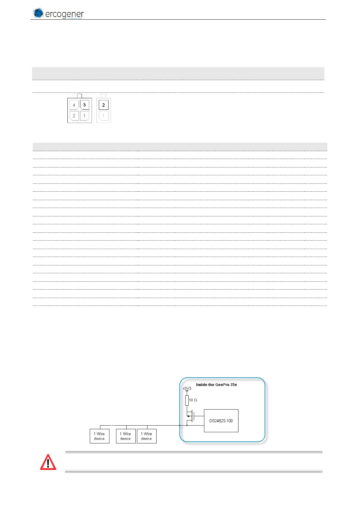
Figure 12 : Internal electrical scheme of the Multi One Wire bus
The integrator has the responsibility to protect the input from electrical perturbations and to
respect the functioning parameters values.