EG_GenPro25e_1055_UG_002_UK
Descriptions and non-contractual illustrations in this document are given as an indication only.
ERCOGENER reserves the right to make any modification.
Dct_427_02
3.5.2 Analog input 0 – 10 V (Option S0434B)
Table 17 : Characteristics of the analog input option S0434B
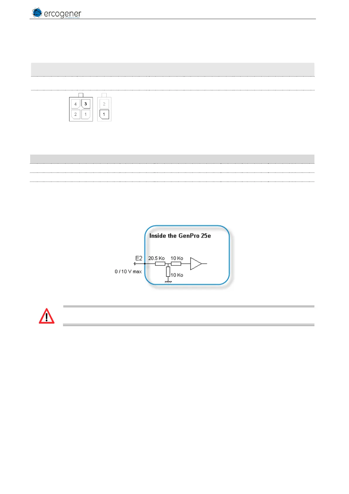
1 Connector 2 pins
3 Connector 4 pins
Corresponds to wires
Yellow for ANA1
Black for GND
see ANNEX 1 - 4-pins Micro-FIT cable (Power supply) et
ANNEX - 2-wire Micro FIT cable connector (Input/Output)
Table 18 : Characteristics of the analog input option S0434B
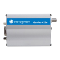
Figure 10 : Internal electrical scheme of the option Analog S0434B
The integrator has the responsibility to protect the input from electric disturbances and to
respect the values of the functioning parameters.