Edition 050614
-- 2 2 --
cu20d2
DESCRIPTION OF OPERATION
This function description describes the function of circuit boards and other components in
the power unit. It is divided into sections, numbered to correspond to the circuit board
numbers and divisions into function blocks.
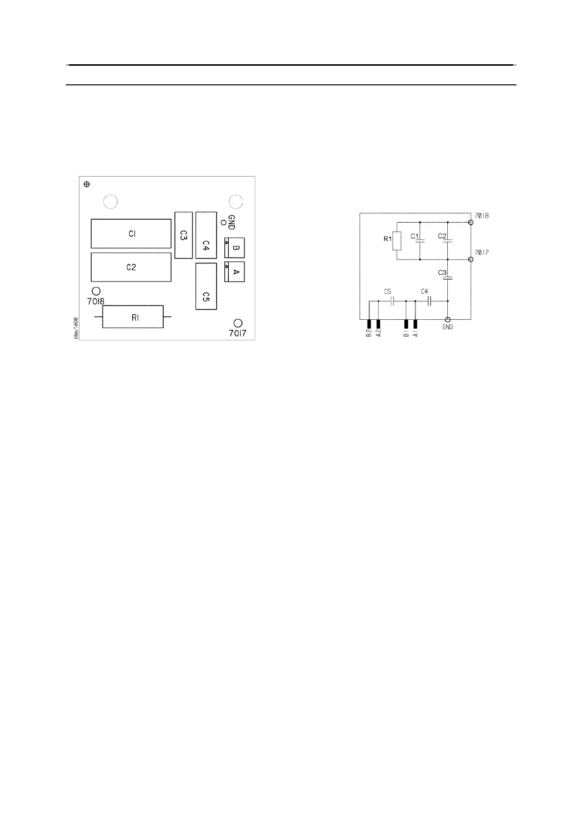
AP2 Interference suppressor board
Component positions and circuit diagram for circuit board AP2
The circuit board removes interference signals.
1 MMC module
The MMC module consists of an operator ’s control panel and a welding data board.
The power unit, the wire feed unit and the control panel each have their own
microprocessor for control, with the control panel being the central unit in the system. In
addition to storing and issuing welding data, it also exercises overall control of the system
as a whole.
Setting the welding data
Man--machine communication (MMC) is assisted by the modular architecture of the Aristo
range. It is possible to choose systems with the emphasis on the simplest possible
operation, or those that can provide more optimised settings for the best welding
performance.
The MMC modules are described in separate service manuals
MMC modules for the AristoMig U400 and AristoMig 400
The MMC module can either be a control panel fitted to the wire feed unit or a control
pendant connected to the remote connection of the power unit or the feed unit.
AristoMig U400: Control panel U6 and AristoPendant U8.
AristoMig 400: Control Panel M2, Control Panel MA4, Control Panel MA6 and
AristoPendant U8.
MMC modules for the AristoTig 400
The power unit is supplied with Control Panel T4 or Control Panel T6.
MMC modules for the AristoArc 400
The power unit is supplied with Control Panel A2 or Control Panel A4.