Edition 050614
-- 5 8 --
clhr1fe2com
10. Repeat the measurements in item 5 to 8 above.
The pulses on outputs C1, C2 and E1, E2 are in phase with each other.
Pulse frequency and duration are controlled by circuit board 20AP2: rise and fall times are
controlled by gate driver board 15AP2.
If the waveform shape, pulse duration and frequency are as described above, the results
are satisfactory and the measurements can be concluded here.
Pulses from circuit board 20AP1 to circuit board 15AP2
Read and follow the instructions on page 56, before you check the pulses. Measure the
pulses when loaded by the pulse transformers on 15AP2.
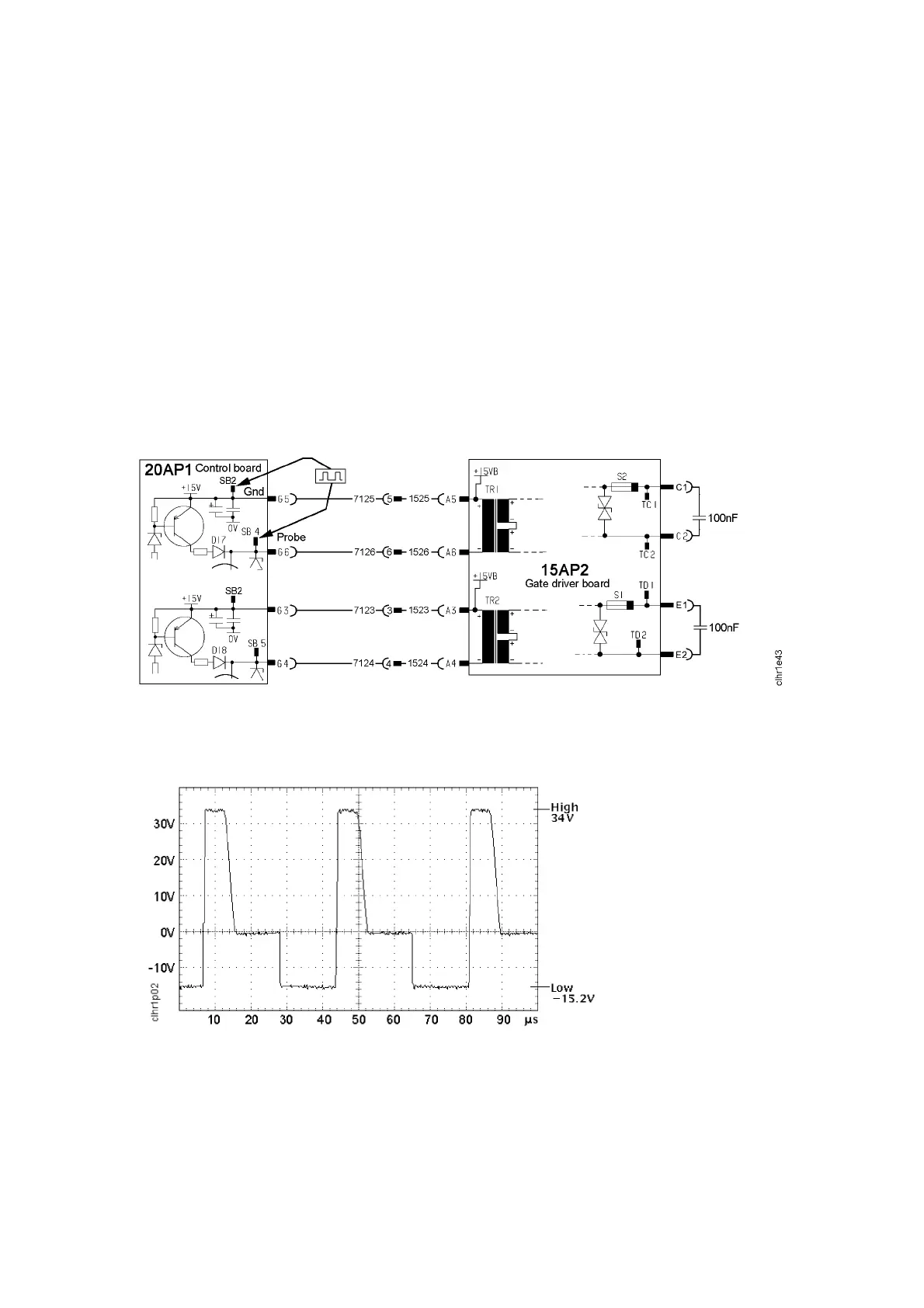
1. Connect an oscilloscope with the screen to SB2 and the probe to SB4.
Test points for the gate pulses
Pulses from 20AP1 Pulses from 15AP2
2. Start the power unit and set it to MMA mode.
3. Compare the waveform of the gate pulses with the diagram below.
The waveform shape must be as in the diagram.
Pulses from 20AP1 to 15AP2 when the output of 20AP1 is connected to 15AP2.
4. Measure the pulse frequency, it must be 27 kHz ±0.5 kHz.
5. Measure the pulse duration, it must be 41 -- 43 % of the cycle time, measured at --10 V
on the negative pulse, as shown in the diagram above.
6. Measure the maximum pulse voltage, it must be in the range 30 -- 38 V.
The minimum voltage must be in the range from --14 to --16 V.
7. Connect the probe to SB5 and the screen to SB2.



 To Next Page