Edition 050614
-- 4 4 --
cu20d_20_2
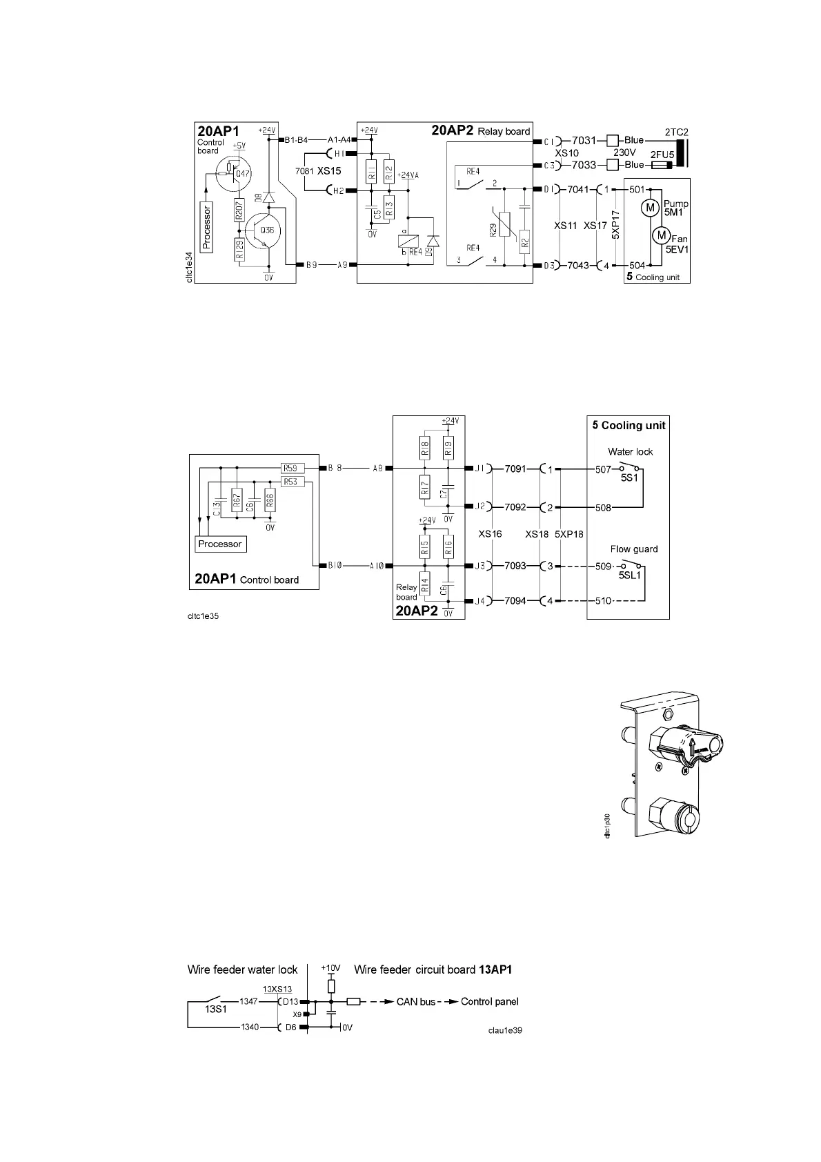
20AP2:4 Power supply to the cooling unit
The cooling water pump is controlled by the software in the welding data unit
via circuit board 20AP1. The connection diagram for the cooling unit is shown
on Page 24.
20AP2:5 Cooling water monitoring in MIG welding mode
Water lock and flow guard in the AristoMig
Microswitch 5S1 in the water lock connector closes when a
cooling water hose is connected to the blue water connector
on the front of the cooling unit. The pump stops if the switch
opens.
In MIG welding mode, the cooling water connection on the
front of the cooler is not used: instead, the water connections
on the back of the unit, which have no wa ter locks, must be
connected to the wire feed unit. However, the cooling water
connections on the front of the wire feed unit do have a water
lock, within which microswitch 13S1 senses if a cooling water
hose is connected, see the diagram below.
Water lock
Contact 5SL1 in the flow guard closes when the water flow rate exceeds 0.7
l/minute. The flow guard is an accessory: if no flow guard is fitted,
connections XS18:3 and XS18:4 are linked.
The following description refers to cooling units with a flow guard: machines
without a flow guard behave as if cooling water is always flowing.
Water lock in the wire feed unit