Edition 050614
-- 2 6 --
clhr1de3pwr
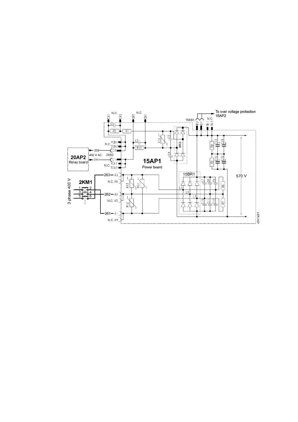
15AP1 Power board
The power board carries the mains rectifier, the charging circuit, the switching circuit and a
transformer for voltage supply to the overvoltage and undervoltage protection.
Circuit board connectors marked NC are not connected.
If this circuit board is to be replaced in machines with serial number prior to 524--xxx--xxx:
See page 69 for instructions.
15AP1:1 Mains rectifier b ridge and charging circuit
When the mains power supply is turned on, smoothing capacitors C13--C16
charge up via rectifier bridge BR2. Contactor 2 KM1 closes after about twelve
seconds and connects the mains supply to rectifier bridge 15BR1. See
Page 43 for a more detailed description of the starting sequence.
Component description:
BR2 Rectifier for charging current.
C1, C2 Capacitors, restricting the inrush charging current to rectifier
bridge BR2. The current while capacitors C13 -- C16 are
charging is about 0.7 A.
C13 -- C16 Smoothing capacitors, with a total capacitance of 1000 mF.
R5, R10 Discharge resistors for C1 and C2.
R1 Series resistor (10 Ω) for the charging current to C13 -- C16.
R8, R9 Potential divider and discharge resistors for C13 -- C16.
R11 -- R13 Varistors. Clip the voltage peaks exceeding about 1000 V.
The varistors do not conduct when the voltage is below 480 V
AC RMS, this corresponds to a peak voltage of 680 V.
15BR1 Main rectifier for mains voltage.



 To Next Page