Edition 050614
-- 5 3 --clhr1fe2com
Dismantling
When dismantling the power unit, start as follows:
1. Remove the screws securing the cover and the rear handle.
2. Pull the cover backwards and lift it off.
3. Remove the side plates.
Service traps
The following are a number of points where it is easy to make a mistake and damage the
equipment.
Main On/Off switch, 2QF1
Don’t get the cable cores mixed up. Connect a ll the cores to the switch in accordance with
their numbers and the terminal numbers on the switch, all as shown in the circuit diagram
for the power unit. If the cores are mixed up and connected to the wrong terminals, there is
a risk o f short--circuiting and burning up relay board 20AP2.
Terminal block, 2XT2
Don’t mix up the wires connected to terminal block 2XT2: take care to connect them as
shown in the circuit diagram. If the wires are mixed up and connected to the wrong
terminals, there is a risk of short--circuiting and burning up relay board 20AP2.
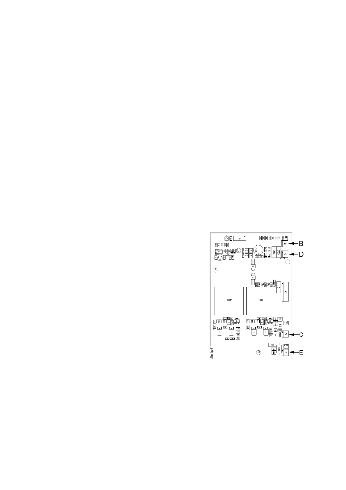
Overvoltage and undervoltage protection
Don’t mix up contacts 15XS7 and 15XS5: if you do, you
write off circuit board 15AP2.
Contact 15XS5 is marked B, and must be connected to
terminal strip B on circuit board 15AP2.
Contact 15XS7 is marked D, and must be connected to
terminal strip D on circuit board 15AP2.
The gate contacts
Make sure that gate contacts 15XS6 and 15XS8 are
connected to terminal strips C and E on circuit board
15AP2 before the power unit is energised.
If the contacts are not connected, the IGBT transistors will
fail.
As the signals from contacts C and E are the same,
mixing them up will not cause a fault.
Circuit board 15AP2
The current senso r
Check that current sensor 15AP3 is connected to control circuit board 20AP1. If it is not,
then there will be no current limit protection, and the power unit can fail.
Power components
Follow the instructions for fitting components to the heat sink. Use thermal contact paste,
and tighten all bolts to the correct torque. Incorrectly mounted components can cause
breakdowns. See the instructions on Page 55.