Edition 050614
-- 5 --cu20d1
INTRODUCTION
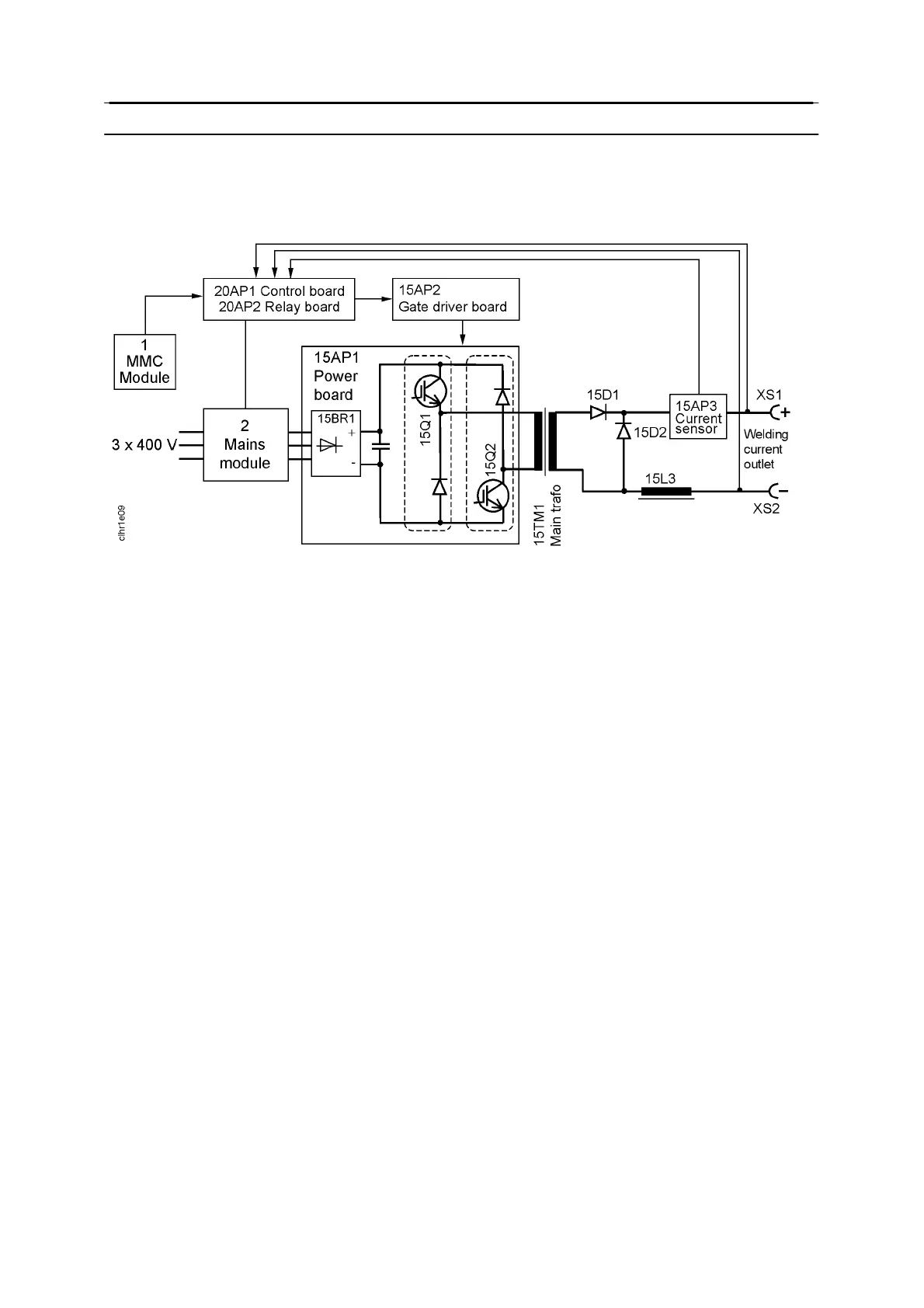
The power source is transistor --controlled, operating on the inverter principle. It consists of a
number of function modules, as shown in the schematic diagram below. Each module has a
module number, which is always included as the first part of the name/identification of
components in the module.
Schematic diagram of the power source
The modules have the following main functions:
1 MMC module
The control panel and welding data unit, which control the machine functions.
2 Mains module
Mains interference suppressor, mains switch, control power transformer, contactor.
15 Power module
This module is a forward converter inverter, operating at a switching frequency of 27 kHz.
IGBT transistors are used a s the switching elements. All power semiconductors are built
into modules in order to ensure a robust design suitable for use in the demanding welding
environment.
20 Processor board module (controller module)
This is the controller board, 20AP1, with a microprocessor, that monitors and controls the
voltage and current. It is served by relay board 20AP2, which handles input and output
signals to/from the controller board.
Further information on the modules can be found in the component and function
descriptions.
 Loading...