Edition 050614
-- 6 5 --
cu20f3
AristoMig, calibration of the arc voltage input
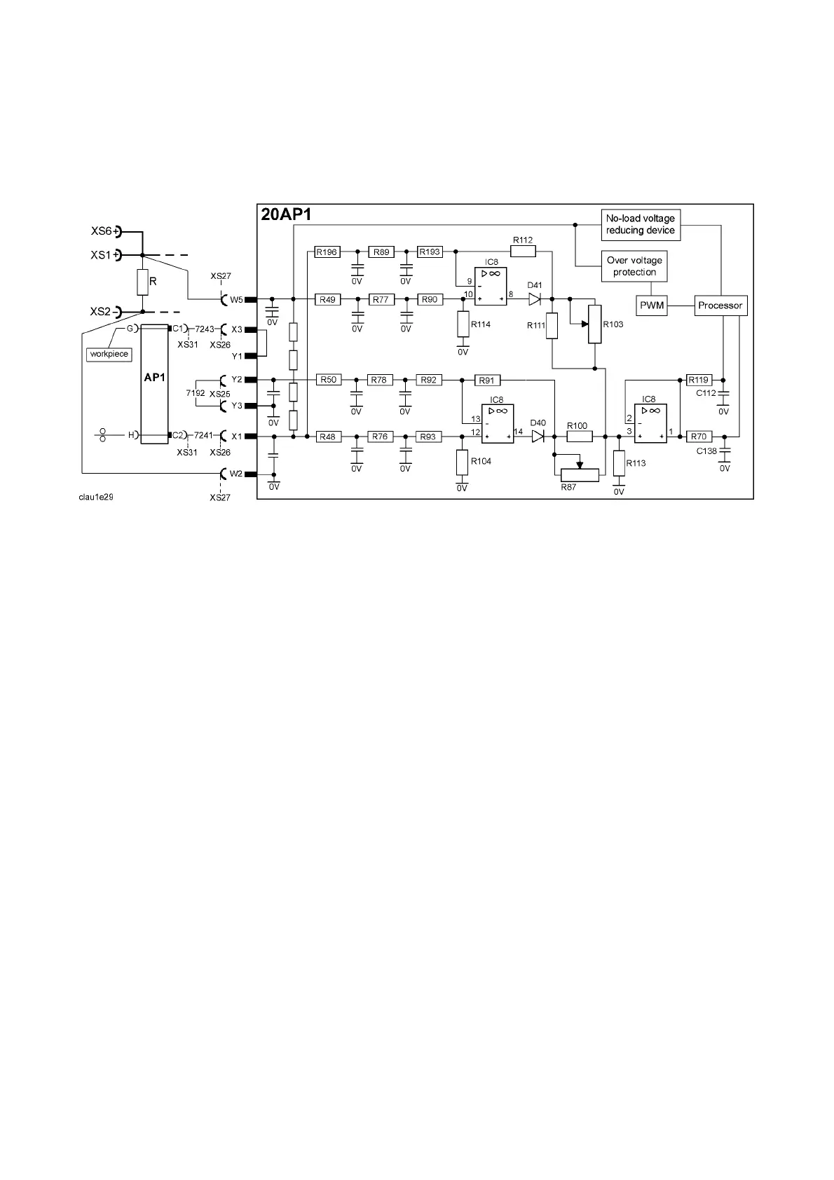
The arc voltage input can be calibrated using trimming potentiometers R87 and R103 on
circuit board 20AP1. The board has been calibrated in the factory: further adjustment
should not normally be necessary.
Circuit diagram of the arc voltage input
Check that there is a short -- circuiting link across connectors Y2 -- Y3: see the circuit
diagram above. Connect a wire feed unit to the power unit. Connect long welding current
cables, to give an appreciable voltage drop in the cables. Connect a wire to the feed rollers,
and connect an external voltmeter, as shown in the diagrams on next page. Set the power
unit to MIG short arc welding mode, and apply a resistive load to give a current of 100 A at
25 -- 30 V.
Start the power unit from the welding gun trigger contact and adjust the current by changing
the wire fed speed setting. Adjust the voltage by varying the load resistor.
Use an accurately calibrated external voltmeter to measure the output voltage of the
machine.