Edition 050614
-- 3 4 --
clhr1de4ctr
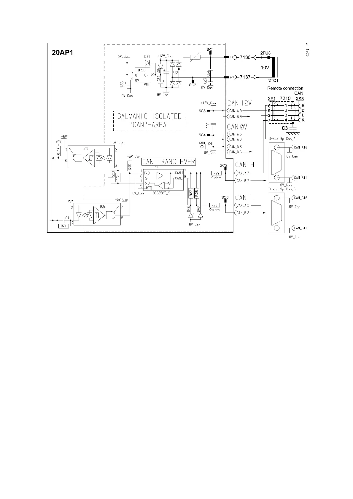
Bus communication circuits to and from the control board
Check the following points in the event of problems with CAN communications:
S The terminating resistor. The CAN bus resistance must lie in the range
50 -- 130 Ù: the optimum value is 60 Ù. To check the resistance, turn off
the power unit and measure the resistance between pins L and K in the
remote control connector socket XS3 on the front of the machine.
S The connection cable between units. Check that the correct type of cable
is being used. Check that each signal is being carried by the correct core.
CAN H and CAN L must be carried by the twinned pair.
S All screen connections must be sound.
S Good contact with the chassis connections from/to the control board,
suppressor board and suppressor capacitors. See the main circuit
diagram.
Terminating resistors
In order to avoid communication interference, the ends of the CAN bus must
be terminated by resistive loads.
One end of the CAN bus is at the control panel, which incorporates a
terminating resistor. The other end is in the power source and it must be fitted
with a terminating resistor. If a CAN remote control with terminating resistor is
connected to the power source, the terminating resistor must be removed from
the power source.