Edition 050614
-- 3 5 --
clhr1de4ctr
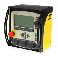
The CAN remote controls and CAN adapters have a built--in terminating
resistor. This resistor can be disconnected or connected by moving a jumper:
See the service manual for the CAN based remote controls (filename 0740 800
170).
Principal diagram of the CAN bus and connecting up of the terminating resistors
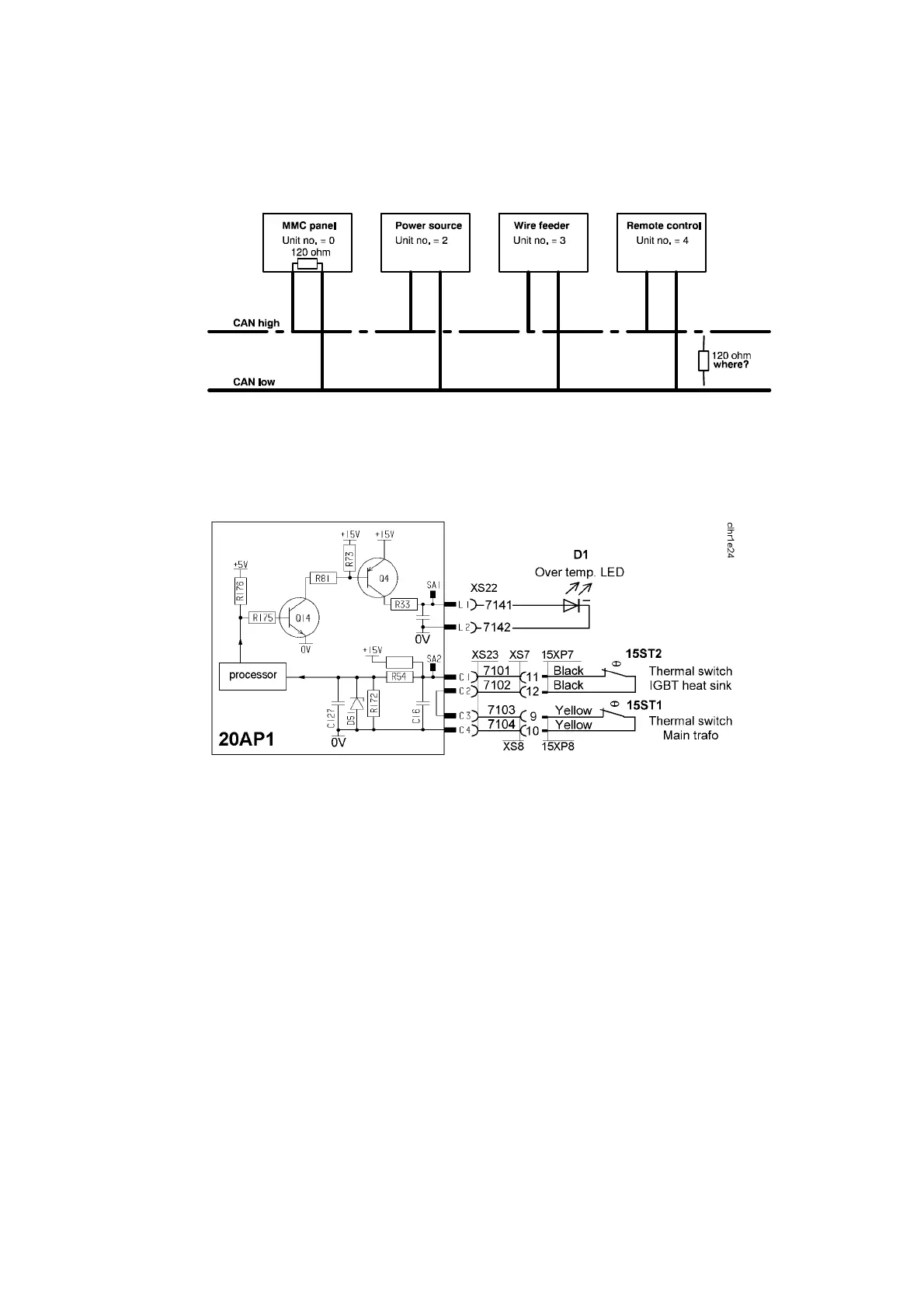
20AP1:4 Temperature monitoring
From serial n umber 105--138--xxxx: Thermal cutout switch 15ST1 is fitted
under the winding of main transformer 15TM1, and opens at a temperature of
130°C. The duty cycle is valid for 40°C.
Thermal cutout switch 15ST2 is mounted on the heat sink, beside the IGBT
transistors, and opens at a temperature of 80°C. See Page 55 for fitting
instructions.
If either of the switches operates, the power unit is stopped and LED D1 on the
front panel lights. The power unit cannot be restarted until it has cooled
sufficient ly for the switch(es) to reclose.
Before serial number 105--138--xxxx: Thermal cutout switch 15ST1 is fitted on
the winding of main transformer 15TM1, and opens at a temperature of 110°C.
The duty cycle is valid for 25°C.
 Loading...