Edition 050614
-- 3 6 --
clhr1de4ctr
20AP1:5 Overvoltage and undervoltage protection
See 15AP2:2 on Page 29.
20AP1:6 Communication with relay b o ard 20AP2
See Page 42, 20AP2 relay board.
20AP1:7 Gate pulses
See Page 29, 15AP2:1 gate driver stage.
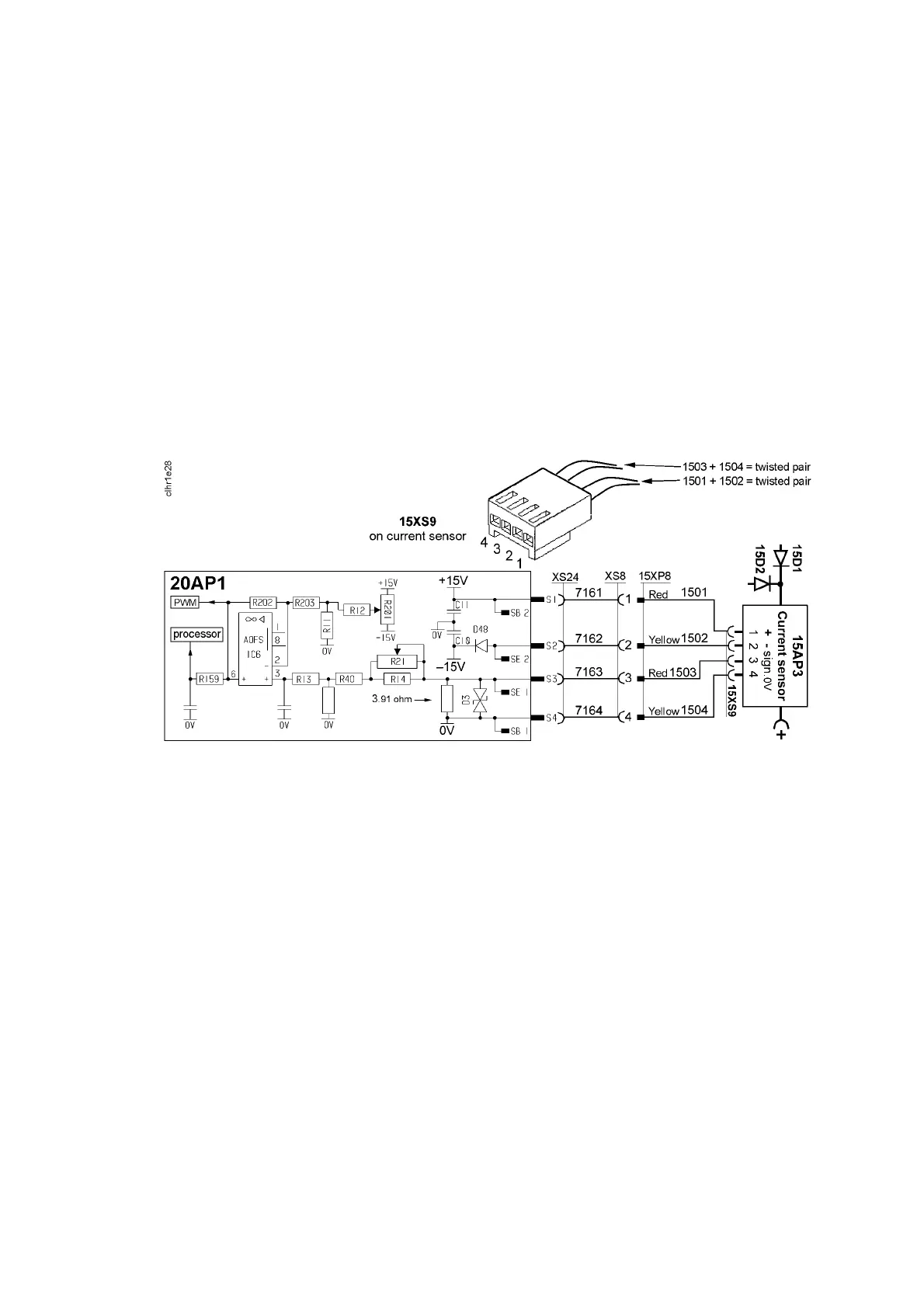
20AP1:8 Current sen so r
The current signal supplied to contact S3 on circuit board 20AP1 is 200 mA at
400 A, and is linearly proportional to the current. Measuring the voltage
between contacts S3 and S4 on circuit board 20AP1 must show 0.195 V at
100 A welding current. (U = R x I ⇒ 3.
91 x0.05 =0.195)
If circuit boards 20AP1 or 15AP3 are replaced, the machine must be
recalibrated. See Page 64 for calibration instructions.
Offset potentiometer R201 is not mounted on circuit board 20AP1. The offset
adjustment is carried out by fixed resistors.
On no load, there must be a voltage of 0 V ±2 mV at input S3 of circuit board
15AP3. If the current sensor gives an incorrect value on no load, it must be
replaced. The sensor must be connected to 20AP1 when making the
measurement.