Edition 050614
-- 6 4 --
clhr1fe2com
Calibrating the current sensor signal
1. If the power unit has a TIG function, remove fuse 2FU5 from transformer 2 TC2. This
disconnects the supply to the HF ignition unit (see the connection diagram).
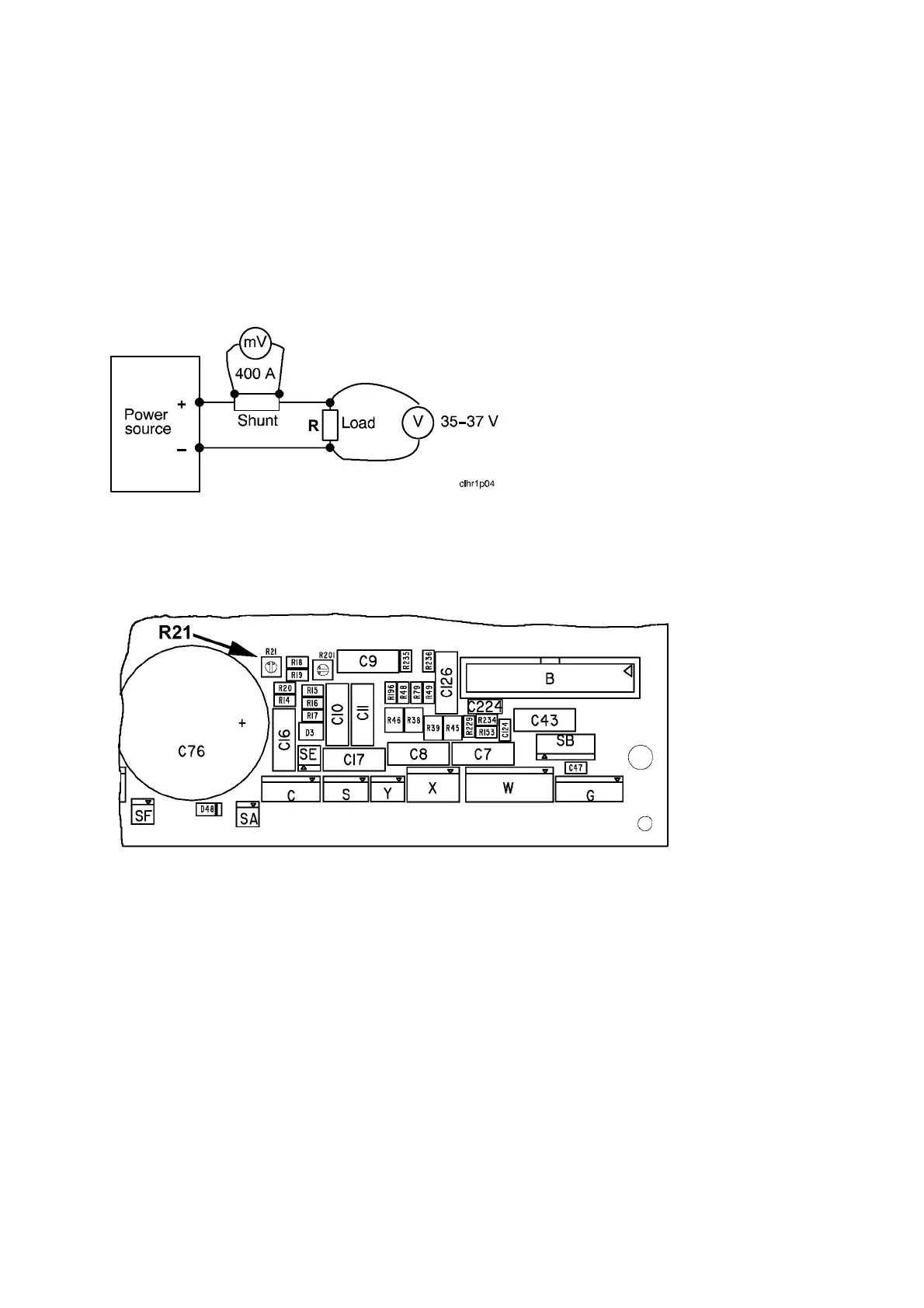
2. Connect the power unit to a resistive load.
3. Connect a calibrated shunt in series with the load.
4. Set a welding current of 400 A.
5. Load the power unit so that the voltage across the load is 35 -- 37 V.
Circuit diagram for current calibration
6. Measure the shunt voltage using a calibrated multimeter.
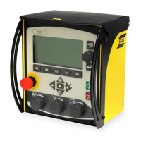
7. Using potentiometer R21 on circuit board 20AP1, adjust the shunt voltage to
corre spond to 400 A ±4A.
Position of potentiometer R21 on circuit board 20AP1.
8. Check the current at low values as well: 16 A at 19 -- 22 V, for which the tolerance is
±1 A. If the current is outside the tolerance, replace current sensor 15AP3.