Edition 050614
-- 4 3 --
cu20d_20_2
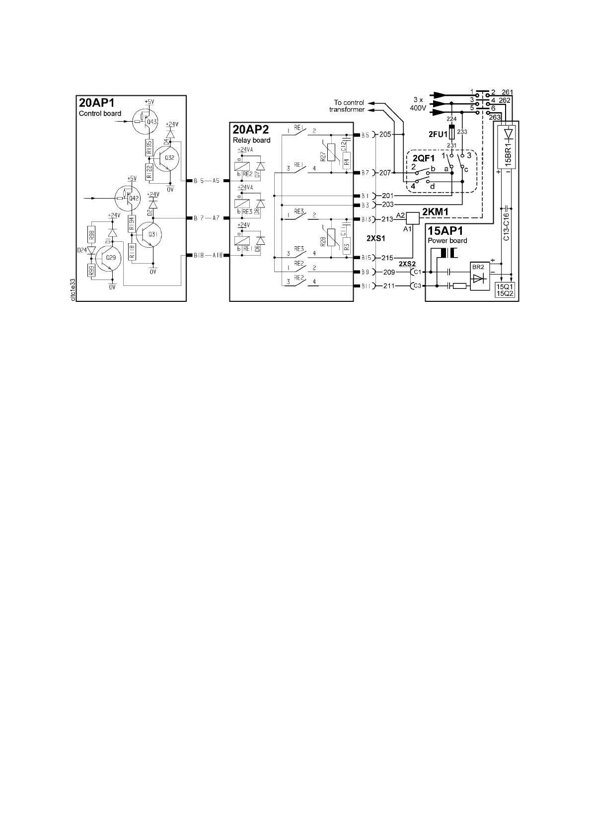
20AP2:3 Starting sequence
Schematic diagram of the power unit starting circuits
Starting sequence:
1. Turning main switch 2QF1 from 0 to 1 closes contacts a--1 and c--3, this
energises the relay contacts on RE1 -- RE3.
2. Turning 2QF1 to the START position closes contacts 2-- b and 4--d.
3. The controller board is energised from the control current transformer.
4. Relay RE1 is energised by transistor Q29.
5. The control power transformer is supplied via contacts 1--2 and 3-- 4 on
relay RE1. The relay is held in via the controller circuit board.
6. When released from the START position, the main switch returns to
Position 1.
7. The software in the MMC module is initiated for about nine seconds.
8. Relay RE2 is activated by transistor Q32.
9. RE2 connects 400 V AC to rectifier bridge BR2 on circuit board 15AP1.
10. After about three seconds, the voltage across smoothing capacitors C13 --
C16 is about 440 V.
11. The overvoltage and undervoltage protection senses whether the voltage
across capacitors C13 -- C16 is within the tolerance range of 330 -- 680 V.
12. If the voltage is within the tolerance range, relay RE3 is activated by
transistor Q31.
If the voltage is outside the tolerance range, the starting sequence is
interrupted at this point. Contactor 2KM1 does not close, and relay RE2
drops off. Machines having an MMC--panel with dispay show fault code 5.
13. RE3 energises main contactor 2KM1, which closes and connects 3--phase
400 V to main rectifier 15BR1.



 To Next Page