P12/62 T-IM114b
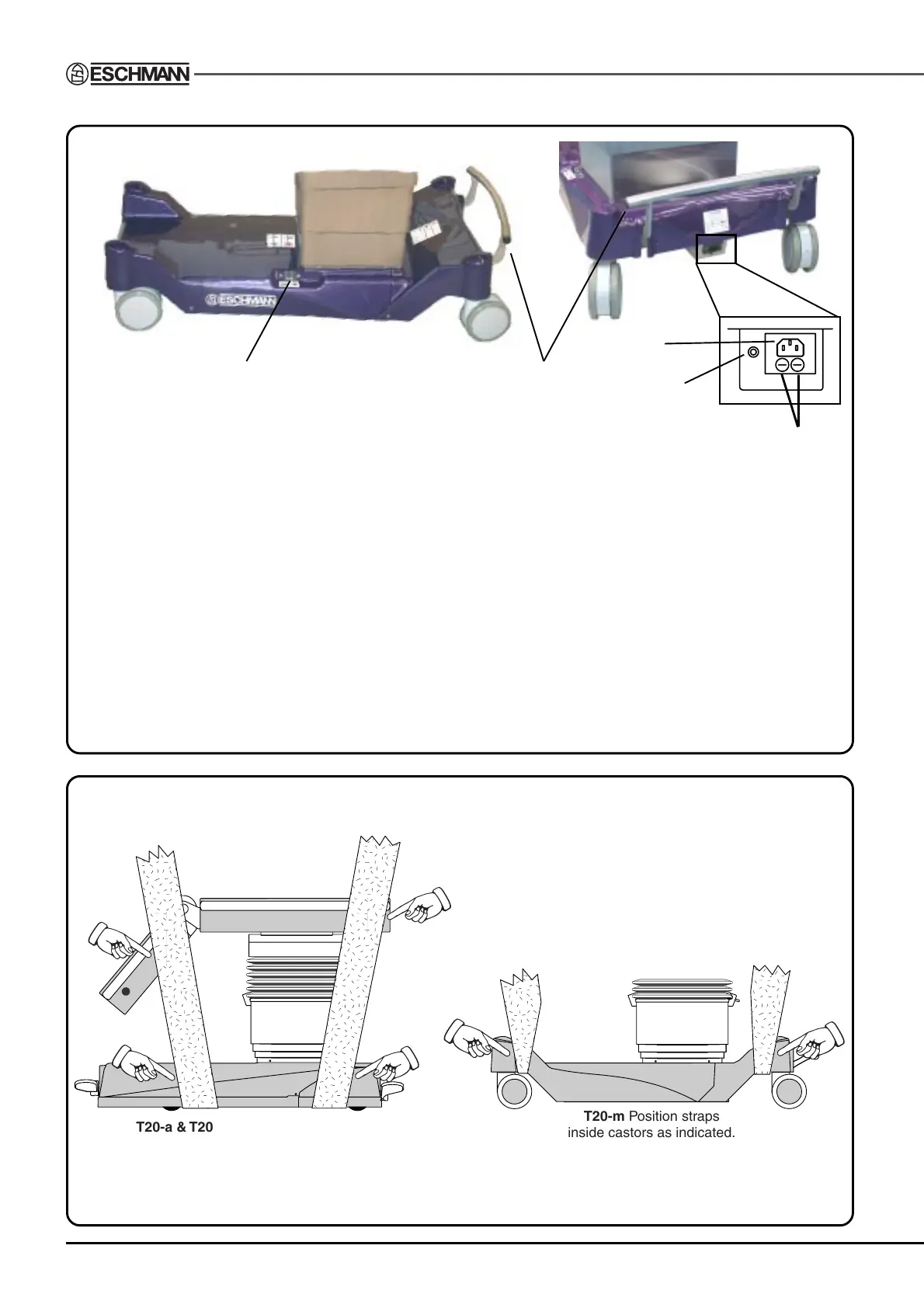
Fig. 2.3 Identification of the main parts of the T20-m table base and column.
T20-m Position straps
inside castors as indicated.
T20-a & T20-s Position straps inside,
but as close as possible to the castors.
Use webbing straps of minimum width 100mm
and a minimum breaking load of 1000kg.
Position adequate padding in the areas indicated
(on both sides) to avoid damaging the table covers.
Fig. 3.1 Lifting the T20 Series operation table
1 Standby battery switch
2 Mains ‘on’ and Battery charging state LED. Red, Amber or Green.
3 Connection socket for mains (ONLY use Eschmann mains cord supplied)
4 Foot pedal
5 Mains fuses
Note: Castor covers (spats) are supplied as an optional item (see section 1.3.12)
The following items on the column are identical to the T20-a table:
Connection socket for Eschmann handset (ONLY) - see item 3, Fig. 2.2
Connection socket for Eschmann footswitch (ONLY) - see item 6, Fig. 2.2
Standby control panel - see item 12, Fig. 2.2
Main table ‘On/Off’ switch - see item 5, Fig. 2.2
Table ‘On’ LED (green) - see item 4, Fig. 2.2
1
5
4
2
3
 Loading...

