P8/62 T-IM114b
2.0 TABLE PARTS AND SYMBOLS
2.1 Part identification
2.1.1 Fig. 2.1 shows the table top in its normal
configuration and identifies the major parts of the table
top.
2.1.2 Fig. 2.2 identifies the various parts of the T20-a
and T20-s table base and column.
2.1.3 Fig. 2.3 identifies the various parts of the T20-m
base.
2.2 Symbols and graphics
To enable an easy reference to all the symbols and graphics
used on the T20 Series of tables (and within these
‘Instructions for use’) the following grouped sections show
all the symbols and graphics used.
2.2.1 Symbols general
The following symbols are shown on various parts of the
table, handset or Serial Number Plate.
IPX 4 This symbol (splash proof) denotes that the
equipment (the table) meets the requirements of IEC529
for protection from splashing water.
IPX 6 This symbol (protection against heavy seas) denotes
that the equipment (the handset) meets the requirements
of IEC529 in that water from heavy seas or water projected
from powerful jets shall not enter in harmful quantities.
This symbol indicates that the equipment is for
use on alternating current.
This symbol indicates that fuses adjacent to the
symbol have a rating and type as detailed.
This symbol warns the user to read the accom-
panying documents, these ‘Instructions for use’.
Symbols and near the main table ‘on/off’
switch, indicate ‘OFF’ and ‘ON’ respectively.
With the mains cord attached the equipment has
‘Class II’ protection against electric shock.
The patient leakage current, with mains voltage
on the applied parts, meets the requirement for
type BF medical electrical equipment and are
defibrillator proof.
This symbol is used to indicate the table’s duty
cycle which is the ratio of the operating time to
the sum of the operating time and the ensuing
interval.
SN This symbol indicates the unit serial number is
as indicated adjacent to the symbol.
REF This symbol indicates the catalogue number is
as indicated adjacent to the symbol.
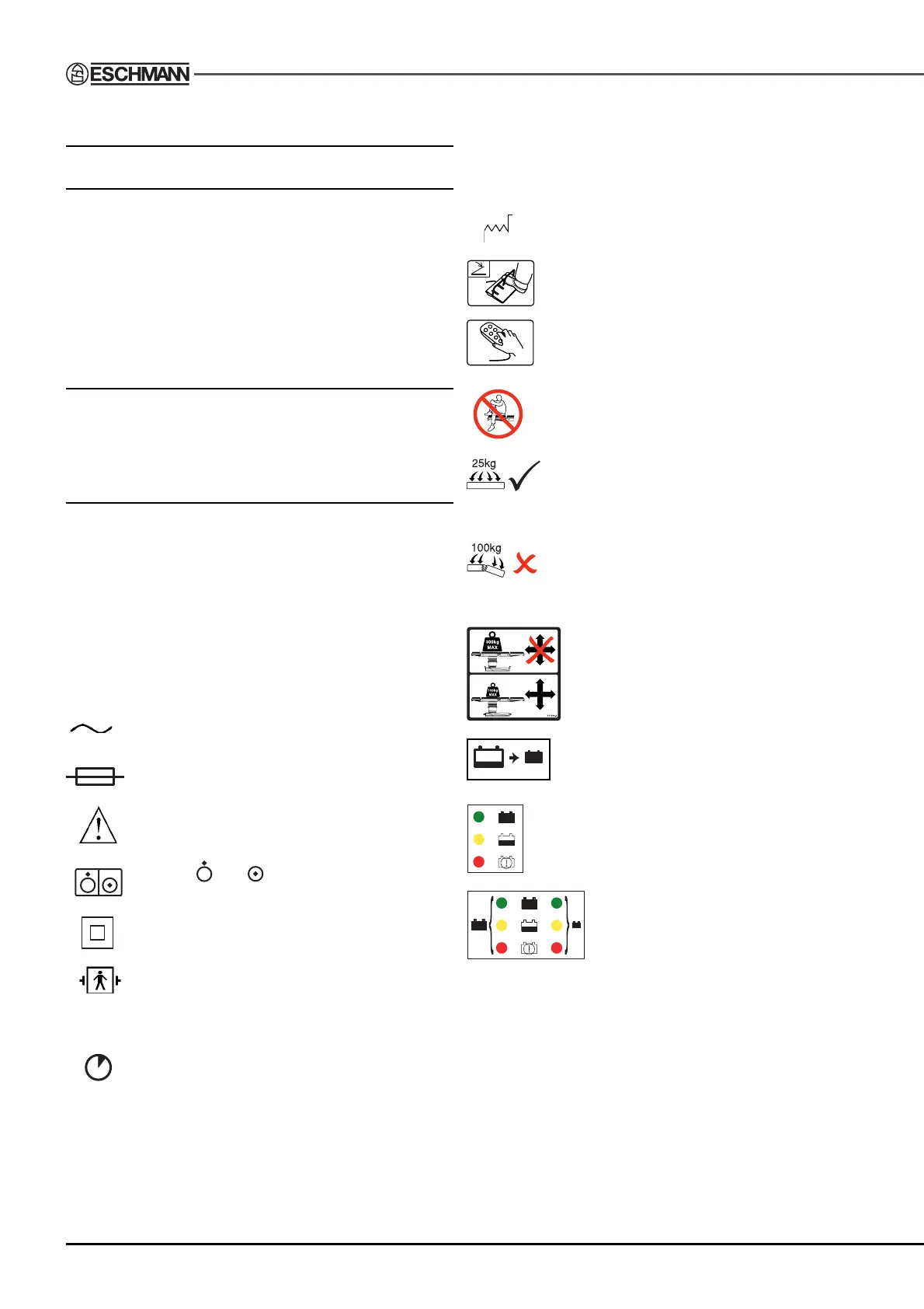
This symbol indicates that the date of manu-
facture is as indicated adjacent to the symbol.
This symbol indicates the connection point for
a footswitch.
This symbol indicates the connection point for
the corded handset.
This symbol indicates that the table section
to which it is applied (e.g. head section, under
the mattress) should not be used as a seat.
This symbol indicates the ‘Safe working load’
of the section to which it is applied can safely
support an evenly distributed load to the value
indicated, in this example 25kg.
This symbol indicates the ‘Minimum breaking
load’ of the section to which it is applied. An
evenly distributed load (in this example 100kg
or greater) may break the section.
This symbol on the table base indicates the
table should not be loaded above 300kg,
nor moved with a load above 135kg for the
T20-a and T20-s tables, or 200kg for the
T20-m table.
This symbol is used to identify the standby
battery switch.
This graphic (T20-m table only) adjacent to the
mains socket, identifies the relationship between
the colour of the mains ‘on’ LED and the battery
charge state, see section 5.3.1.
This graphic (T20-a and T20-s tables
only) adjacent to the mains socket,
identifies the relationship between the
colour of the mains ‘on’ LED and the
battery charge state for the main and
standby batteries, see section 5.3.1.
113150-01