P28/62 T-IM114b
5.3.2.2 Tabletop motions
WARNING
Ensure you have read and understood the
safety warnings listed in section 4.1 and 5.3.2
before using any of the powered motions.
All powered tabletop movements are programmed to
provide a gentle transition from stationary into the required
motion and back again to stationary (i.e. initially the motion
starts slowly and then speeds up to maximum speed and
then slows again before coming to a stop). This also
enables accurate positioning at slow speed by using
repeated short button presses. Alternatively long duration
button presses allow large changes in tabletop position at
maximum speed.
To operate the tabletop powered motions the table must
be switched ‘on’ ( ) at the table on/off switch (item 5,
Fig. 2.2). The table will emit a single ‘beep’ and the green
LED (item 4, Fig. 2.2) will illuminate to show the table is
‘on’. The LED will be bright during use but only dim if the
operating system has gone into ‘sleep’ mode (saving
battery power). The table will instantly respond to any
control input even when in ‘sleep’ mode. Also see section
8.1.
If two buttons are pressed on a handset or footswitch at
the same time neither will have any effect. The function of
the second button pressed is ignored and automatically
cancels the function of the first button pressed and any
table motion stops. Releasing either of the buttons will
enable the function of the remaining button (if still pressed)
to be actioned. This is to eliminate multiple button activation
errors.
Most powered tabletop motions will pause briefly when
they pass through the level position (Note: not applicable
to height and traverse). This is to enable each motion to
be returned to a level position individually.
Be aware that a lowered leg section could hit the table base
when the top is lowered, or the head section could collide
with an anaesthetist’s chair during a Trendelenburg
movement.
Always ensure that there is adequate space around the
table for the movement selected and that the movement
required will not cause injury to patient or medical
personnel. Look for possible trap and or pinch points
between parts of the table and stationary objects.
5.3.3 Using the handset
5.3.3.1 General
WARNING
Do not plug two handsets into the table at the
same time. When two handsets are connected,
neither handset will operate the table.
The corded handset will operate any T20 operation table
(note that the infrared handset is configured to match a
specific table). Input from the corded handset will override
any signals from an infrared handset. The corded handset
simply plugs into either of the table handset sockets (item 3
of Fig. 2.2 and item 2, Fig. 5.11). Never plug handsets into
both sockets at the same time. See section 5.3.3.2 for
details of button function and section 5.3.1.1 for an
explanation of the battery state LEDs.
When using the corded handset always ensure that the cord
is well clear of any moving parts, pinch points and possible
entrapment from table movements. Also ensure that the cord
will cater for any table movement and that such table
movements do not stretch the cord excessively.
When not in use it is suggested the handset is clipped onto
the accessory side rail (item 7, Fig. 2.1). Note that when
clipped onto the table in this way it can be operated with
one finger, without the need to hold it in the other hand. The
handset must be compatible with the side rail fitted to the
table, see sections 1.1.2. The UK handset will also clip onto
head/leg end blocks (item 9, Fig. 2.1).
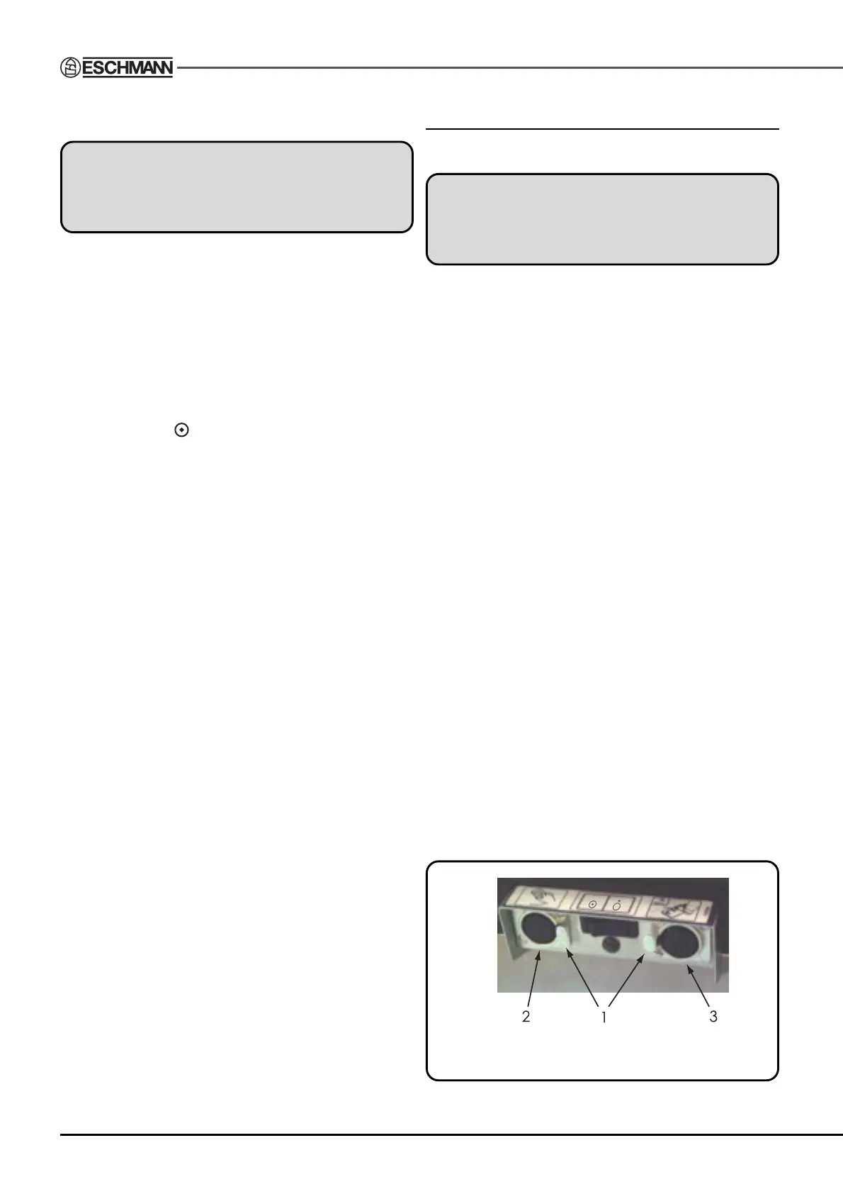
To remove the handset plug from its socket the release
button (item 1, Fig. 5.11) must be pressed and held in during
removal. When removing the corded handset plug from its
socket always grip and pull the plug, do not pull the cord
only as this may damage the cord or internal connections.
Handset buttons provide a tactile feedback to enable the
user to detect when a button has been pressed or released,
this is in the form of a ‘pop’ or ‘click’. Also, all buttons are
‘de-bounced’ to ensure that only deliberate button presses
are responded to (i.e. an accidental quick activation is
ignored).
Fig. 5.11 Controller sockets and
release buttons