T-IM114b P31/62
T20
Series
OPERATION TABLE
5.3.4 Using the standby control panel
WARNING
The standby control panel MUST be used with
extreme care for Trendelenburg movements. All
programmed safety features are overridden in
this mode (e.g. should the tabletop hit an
object, motor protection is inhibited and
damage to them could occur). Also do not
exceed 30° of Trendelenburg (or reverse) from
the standby panel.
The standby control panel is located on the side of the
column (item 12, Fig. 2.2). The panel has five function
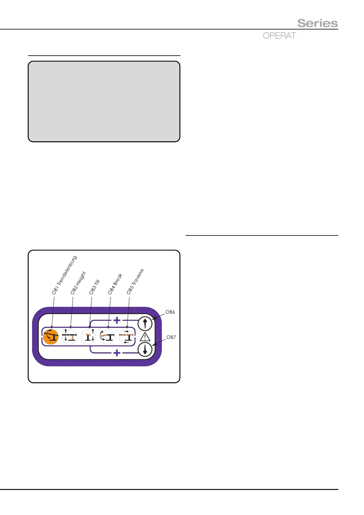
buttons (OB1 to OB5, see Fig. 5.13) and two direction
buttons (OB6 and OB7, see Fig. 5.13). The motion of the
function button is described by its graphical symbol
(symbols are shown and detailed in section 2.2.4).
When controlling the tabletop from this standby control
panel certain inbuilt safety features are overridden. Also
there is no ‘soft start’ to the powered Trendelenburg
movements and the tabletop will not pause as it passes
through the level (Trendelenburg) position. Only five
functions can be controlled from this panel Trendelenburg,
Height, Tilt, Break and Traverse.
Fig. 5.13 Standby control panel
To operate the tabletop from this panel select a required
function by ‘pressing and holding’ a function button
(i.e. OB1 to OB5, Fig. 5.13) and then select a direction for
this function by ‘pressing and holding’ a direction button
(i.e. OB6 or OB7, Fig. 5.13).
Pressing the upper or lower direction button will select the
direction indicated by the corresponding arrow on the
function button. The table will move whilst both the function
button and the direction button are pressed, releasing either
will stop the motion. Motions for each button are fully
detailed in the following sections.
OB1 Trendelenburg - Press and hold this button, then
press required direction button to rotate the tabletop in
the Trendelenburg (button OB6, Fig. 5.13) or reverse
Trendelenburg direction (button OB7, Fig. 5.13)
OB2 Height - Press and hold this button, then press
required direction button to change the height of the
tabletop (button OB6, Fig. 5.13 is for Height up;
button OB7, Fig. 5.13 is for Height down).
OB3 Tilt - Press and hold this button, then press
the required direction button to tilt the tabletop
(button OB6, Fig. 5.13 is for Tilt down on the left;
button OB7, Fig. 5.13 is for Tilt down on the right,
when viewed from the long trunk end of the table).
OB4 Break - Press and hold this button, then press
required direction button to move the tabletop in the
Break up or Flexion direction (button OB6, Fig. 5.13)
or Break down or Extension direction (button OB7,
Fig. 5.13).
OB5 Traverse - Press and hold this button, then
press required direction button to traverse the
tabletop (button OB6, Fig. 5.13 is for cranially; button
OB7, Fig. 5.13 is for caudally).
5.3.5 Fuse replacement
The fuses are located as shown in Fig. 2.2 items 2 and 13
for T20-a and T20-s tables and Fig. 2.3 item 5 for the T20-m
table. Fuses adjacent to the mains inlet socket are only
applicable to the mains supply for the battery charger.
Fuses in the side of the table base adjacent to standby
battery switch (T20-a and T20-s tables ONLY) are
applicable to the main batteries and standby batteries.
These fuses are replaced as follows:-
i Remove the mains cord from the table before
replacing any of the fuses and switch the table ‘off’
with switch item 5, Fig. 2.2.
ii Turn the fuse cover cap anticlockwise to remove
the cap with the fuse inside.
iii Ensure you have the correct fuse (consult the
markings adjacent to the fuse or the Technical Data,
section 9.0).
iv Place the new fuse into the cap and replace the cap
by screwing it in clockwise.

 Loading...
