T-IM114b P23/62
T20
Series
OPERATION TABLE
5.2 Using the removable sections.
WARNING
Ensure that nothing becomes trapped
(e.g. fingers, tubing, cords) when attaching
tabletop sections. When removing a section be
prepared to support the full weight of the
section when the guide pins disengage. Always
carry the section holding the side rails. Never
hold or pick up the section using the black
gas support struts and take care not to operate
the release handle accidentally. Do not operate
the release handle when the section is removed
from the table. For users of small stature, when
handling larger sections (e.g. the leg section)
two people should work together to avoid strain
injuries. Also to minimise weight for all users
remove mattresses before fitting or removing
a section. Users of earlier Eschmann tables
(e.g. MR and RX Series) should note that T20
guide pins are shorter and disengage earlier.
Always ensure that the sections have been
correctly and securely fitted before use and
only use the correct Eschmann sections.
During long term storage of a section it should be positioned
with the pins up, this ensures continued lubrication of the
gas spring seals (e.g. attached to the table and fully
lowered). If stored separately from the table take care not
to actuate the release handle during storage since this will
alter alignment of the pins. Should this happen inadvertently
see section 5.2.1. For short term storage and to aid manual
handling (e.g. during section reversal) use of the ‘T’ series
Head/Leg accessory trolley (REF TA-040013) is
recommended.
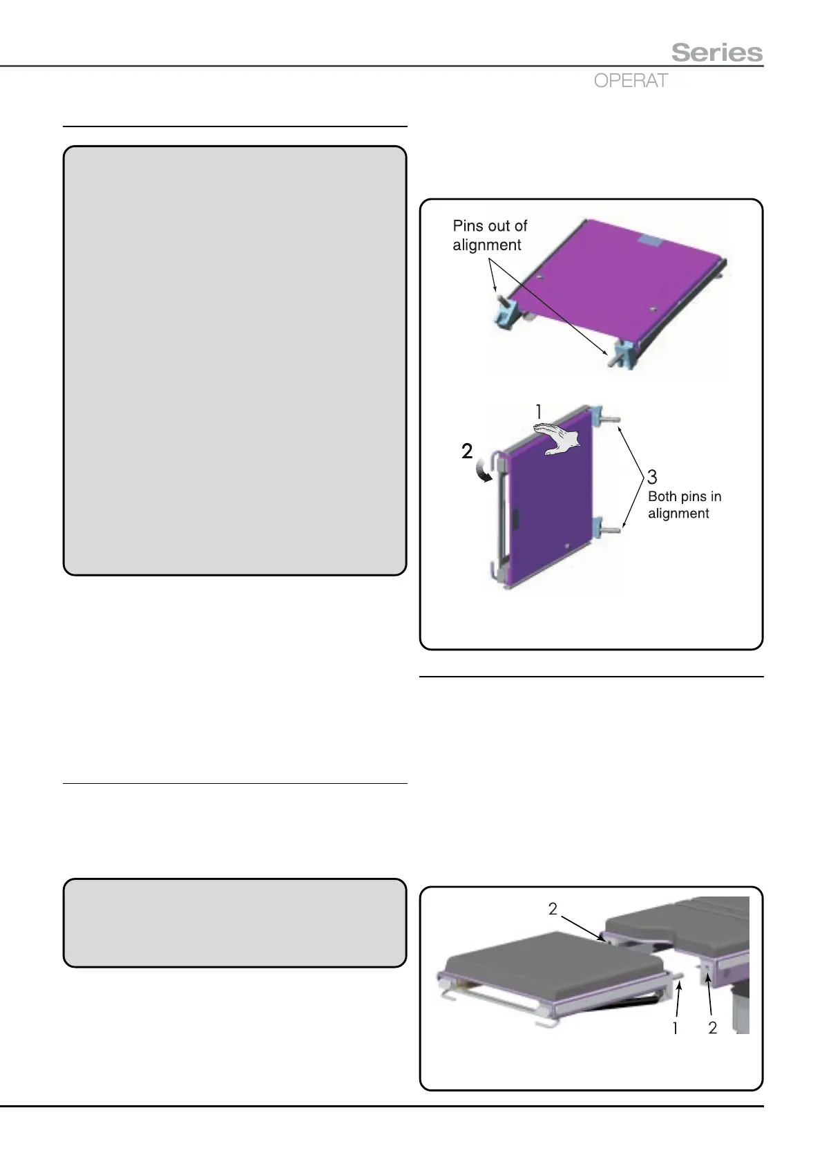
5.2.1 Re-aligning a section’s pins
Realignment of a section’s pins is only required if they have
become mis-aligned whilst the section has been removed
from the table (see Fig. 5.6 for illustration of aligned and
mis-aligned pins).
WARNING
Take care when realigning a sections pins. Ensure
that fingers are clear of the gas springs during
actuation of the release handle.
To realign the pins of a table section place the section on
its side (see Fig. 5.6) and support it by its upper side rail
only keeping fingers etc. well clear of the gas springs
(see 1, Fig. 5.6). Then actuate the release bar (see 2,
Fig. 5.6) until the gas springs have moved both pins to the
ends of their travel as shown (see 3, Fig. 5.6).
To attach the section to a table after re-aligning the pins
insert the pins into the tabletop for 90% of their length,
actuate the release handle and adjust the section until
horizontal and then push the section fully home until the
locking catches engage (also see section 5.2.2).
Fig. 5.6 Section pin alignment
5.2.2 Attaching a removable section
When attaching a section first check to see if the pins are
aligned with each other. It is possible that during storage
the release handle may have been actuated and the pins
are no longer aligned as shown in Fig. 5.6. If they are aligned
attach the section as detailed below, if they are not, align
them and attach the section as detailed in section 5.2.1.
To attach the removable tabletop sections (i.e. head or
leg) hold the section firmly with two hands aligning the pins
of the section (item 1, Fig. 5.7) with the location holes
(item 2, Fig. 5.7) in the fixed tabletop section as shown in
Fig. 5.7.
Fig. 5.7 Aligning section pre-attachment
 Loading...

