Hardware overview/installation IP Series Installation Manual
B.8
Site cabling requirements
Proper data network cabling is an important component of a reliable IP telephony installation. All
cabling for the IP Series PBX and IP Feature Phones should meet IEEE 802.3 requirements or
EIA/TIA 568B Commercial Building Telecommunications Cabling Standards:
• If the IP Series PBX and IP Feature Phones are to be connected to a 100Base-T Ethernet network,
the cable length between the IP Feature Phone and the hub or switch cannot exceed 100 meters
(approximately 328 feet). The IEEE 802.3 standard does allow up to two repeaters (Ethernet
hubs or switches) for extending the distance to the IP Feature Phone.
• If the IP Series PBX and IP Feature Phones are to be connected to a 10Base-T Ethernet network,
the cable length between the IP Feature Phone and the hub or switch cannot exceed 600 feet. The
distance can be extended with the addition of up to two repeaters (Ethernet hubs or switches).
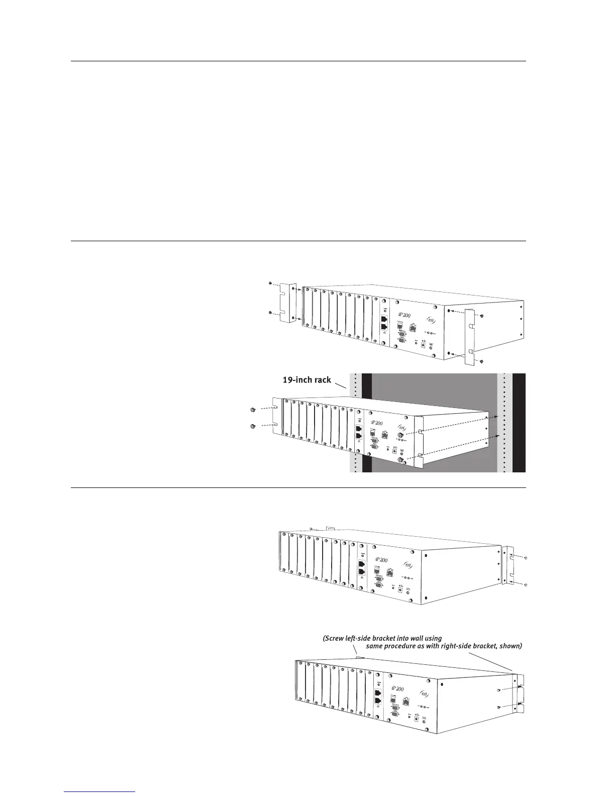
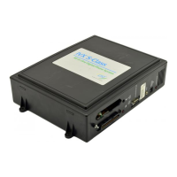
Rack-mounting the IP 200
1. Screw the optional “ears” onto the
forward side-screw receptacles of
the IP 200 chassis.
2. Mount the IP 200 chassis on
the rack.
Wall-mounting the IP 200
1. Screw the optional “ears” onto the
rear side-screw receptacles of the
IP 200 chassis.
2. Mount the IP 200 chassis onto the wall.