Page 10
GSM500 hardware description
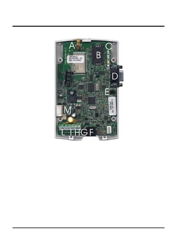
Remove the cover by pressing the upper side.
A ANTENNA cable connector
B SIM CARD housing with front panel
C LED indicating signal strength (green), LED indicating device operation status
(red), LED indicating line status / data transmission (white) and LED indicating
power supply status (blue)
D Female DB-9 connector (.net models only)
E Jumper (.net model only)
F Telephone line output (RJ11 connector) for telephone set connection or PABX
analogue line connection
G 230Vac external adapter input
H Telephone line output (terminal block) for connection of autodialer/PABX
analogue line
I 12Vdc power supply terminal block
L Relay terminal block (R2R model only)
M Backup battery connector (GC, R2R and .net models only)
 Loading...