Jumpers and connectors
Issue G 41
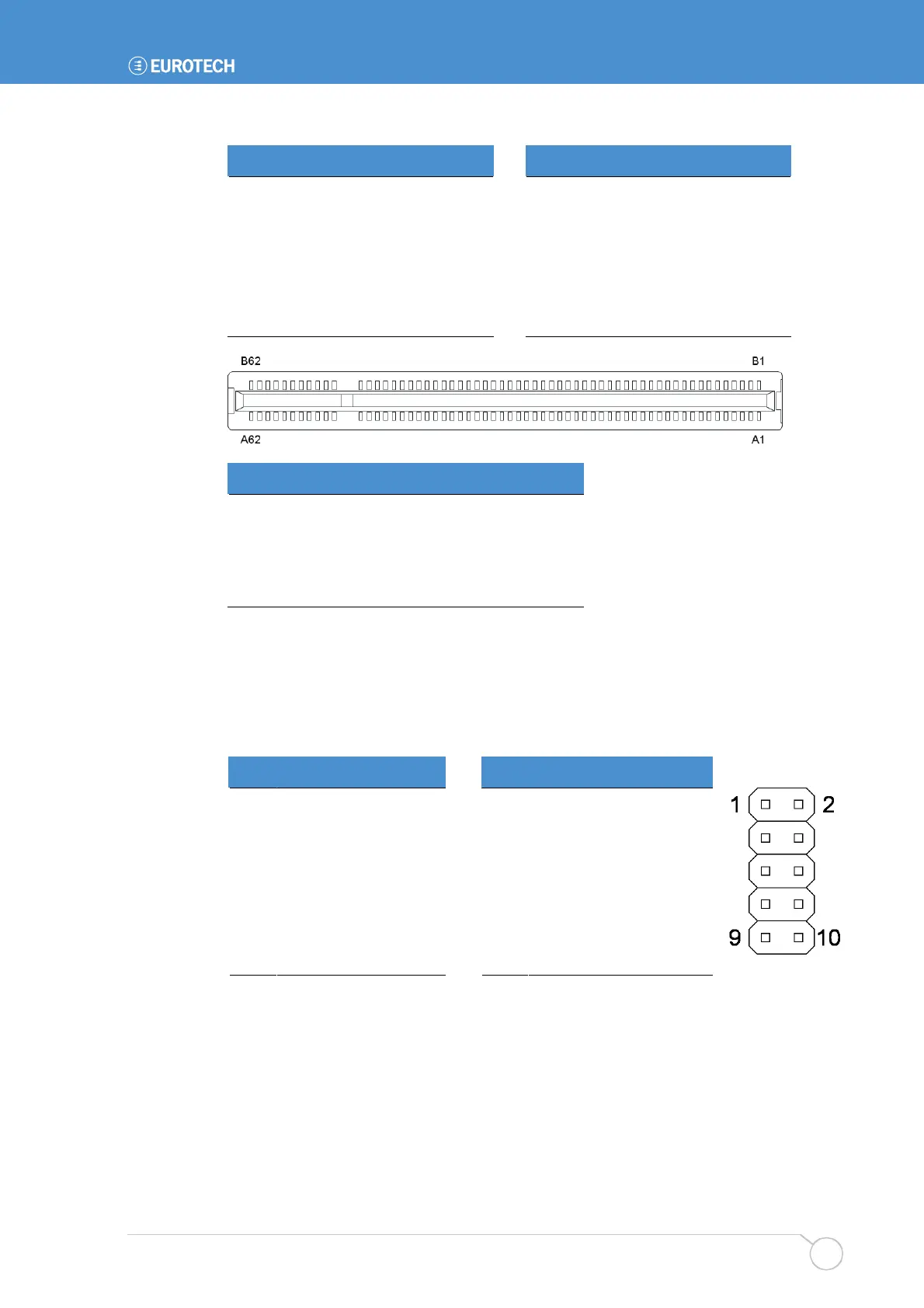
Pin Side B Side A Pin Side B Side A
27 AD23 +3.3V 58 AD01 AD00
28 Ground AD22 59 +5V(I/O) +5V(I/O)
29 AD21 AD20 60 /ACK64 /REQ64
30 AD19 Ground 61 +5V +5V
31 +3.3V AD18 62 +5V +5V
Slot IDSEL GNT/RQT
0 AD27 1
1 AD29 3
2 AD31 4 (JP1 jumper selected)
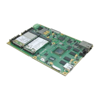
J14 – System control interface
10-way, 2.54mm (0.1") x 2.54mm (0.1") dual row header.
Mating connector: Harwin M20-1070500
Mating connector crimps: Harwin M20-1180022
Pin Signal name Pin Signal name
1 Tamper 2 Ground
3 Power Button 4 Ground
5 System Reset 6 Ground
7 +5V 8 HDD LED
9 PC speaker 10 Ground