EVCO S.p.A. c-pro 3 | Hardware manual ver. 2.0 | Code 114CP3E204
page 14 of 86
4. ELECTRICAL CONNECTION
4.1. Electrical connection c-pro 3 hecto and c-pro 3 hecto+
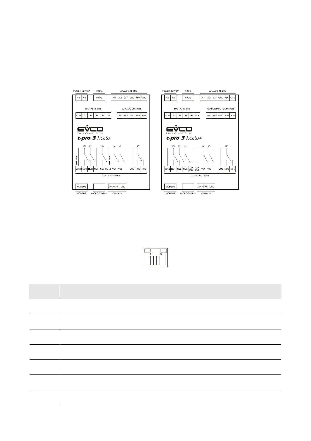
4.1.1. Meaning of the connectors of c-pro 3 hecto and of c-pro 3 hecto+
The following drawing shows the connectors of c-pro 3 hecto and of c-pro 3 hecto.
The following tables show the meaning of the connectors.
MODBUS
RS-485 port with Modbus master / slave communication protocol (configurable via application software).
The following drawing shows the aspect of the RS-485 port.
The following table shows the meaning of the pins of the RS-485 port.
Pin Meaning
1 common
2 not connected
3 not connected
4 D0 = B = - (terminal 0 of the transceiver)
5 D1 = A = + (terminal 1 of the transceiver)
6 not connected
7 not connected

 Loading...


