EVCO S.p.A. c-pro 3 | Hardware manual ver. 2.0 | Code 114CP3E204
page 31 of 86
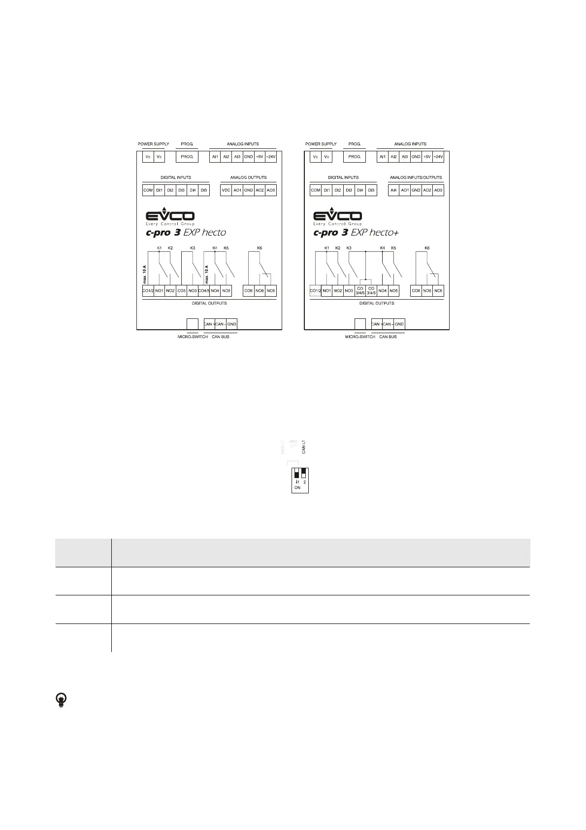
4.3. Electrical connection c-pro 3 EXP hecto and c-pro 3 EXP hecto+
4.3.1. Meaning of the connectors of c-pro 3 EXP hecto and of c-pro 3 EXP hecto+
The following drawing shows the connectors of c-pro 3 EXP hecto and of c-pro 3 EXP hecto+.
The following tables show the meaning of the connectors.
MICRO-SWITCH
Micro switch to plug in the termination of the CAN port (120 Ω, 0.5 W); position micro-switch 2 on position ON to plug in the termination
of the CAN port (plug in the termination of the first and of the last element of the network).
CAN BUS
CAN port.
Terminal Meaning
CAN + signal +
CAN - signal -
GND ground
The maximum number of devices that can make a CAN network (32) depends on the bus load; the bus load depends on the baud rate
of the CANbus communication and on the kind of device in the network.
For example: a CAN network can be made of a programmable controller, of four I / O expansions and of four user interfaces
with baud rate 500,000 baud.

 Loading...


