EVCO S.p.A. c-pro 3 | Hardware manual ver. 2.0 | Code 114CP3E204
page 27 of 86
NO8 normally open contact digital output 8
NC8 normally closed contact digital output 8
The maximum length of the connecting cables of the digital outputs is 100 m (328 ft).
The maximum current allowed on the loads is 10 A.
BMS CONNECTIVITY SLOT (in c-pro 3 NODE mega only)
Slot for gateway c-pro 3 plug-in; also look at the User guide of c-pro 3 plug-in.
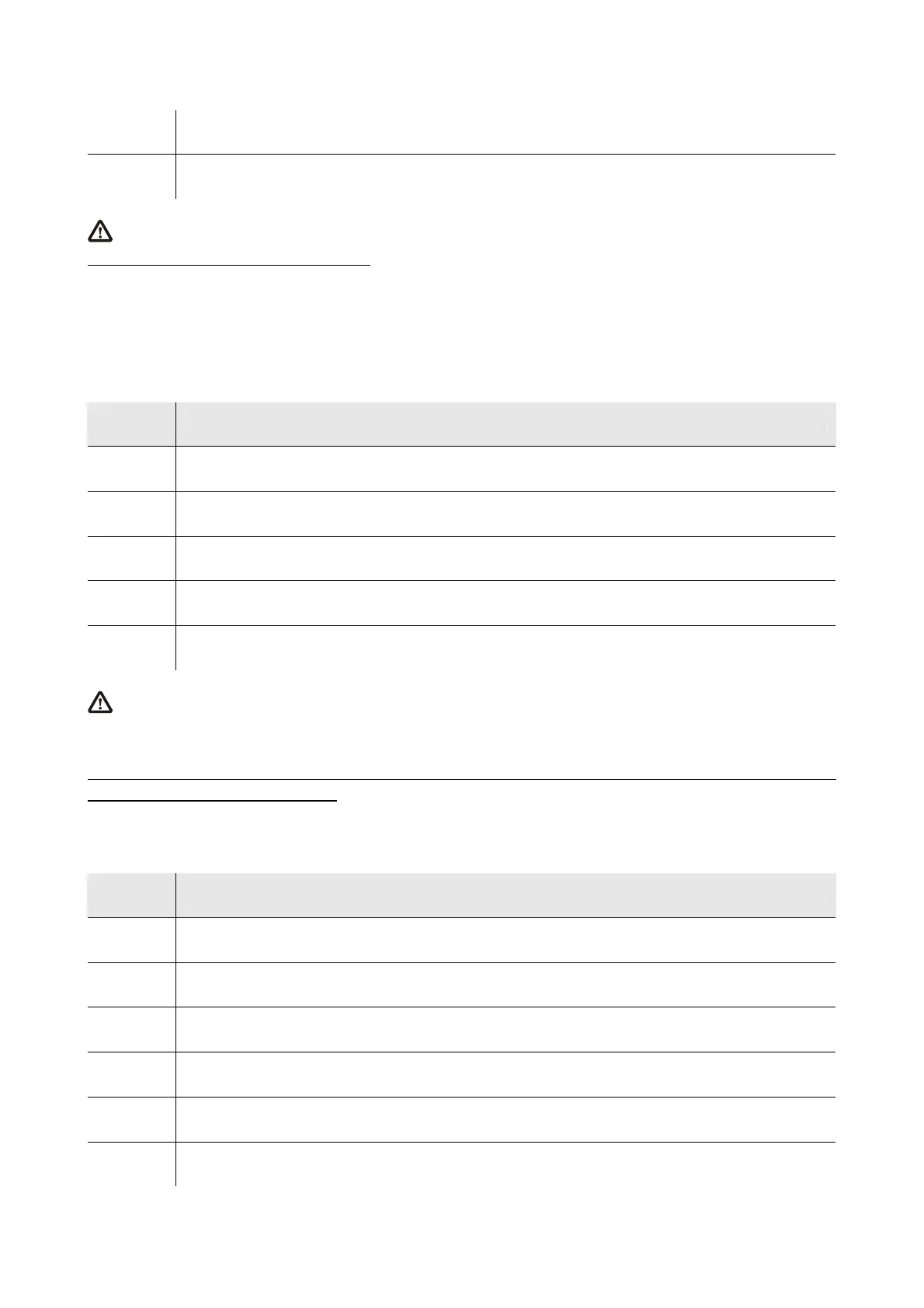
ANALOG OUTPUTS
Analog outputs.
Terminal Meaning
VDC power supply driving analog output 1 (24 VDC, 50 mA max.)
AO1 analog output 1 (PWM signal)
GND ground
AO2 analog output 2 (configurable via configuration parameter for 0-20 mA / 4-20 mA / 0-10 V signal)
AO3 analog output 3 (configurable via configuration parameter for 0-20 mA / 4-20 mA / 0-10 V signal)
The maximum length of the connecting cables of the PWM analog output is 1 m (3.280 ft); the one of the connecting cables of
the 0-20 mA / 4-20 mA / 0-10 V analog outputs is instead of 30 m (98 ft).
For the settings about the analog outputs look at chapter 6 “CONFIGURATION”.
The analog output 1 is usable on condition that the controller is powered in alternate current and the phase powering the controller is the
same powering the user driven by the output.
DIGITAL INPUTS
Digital inputs.
Terminal Meaning
DI1 digital input 1
DI2 digital input 2
DI3 digital input 3
DI4 digital input 4
DI5 digital input 5
DI6 digital input 6

 Loading...


