6
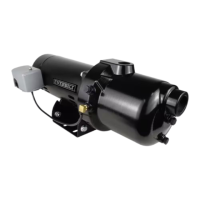
Shallow Well Installation
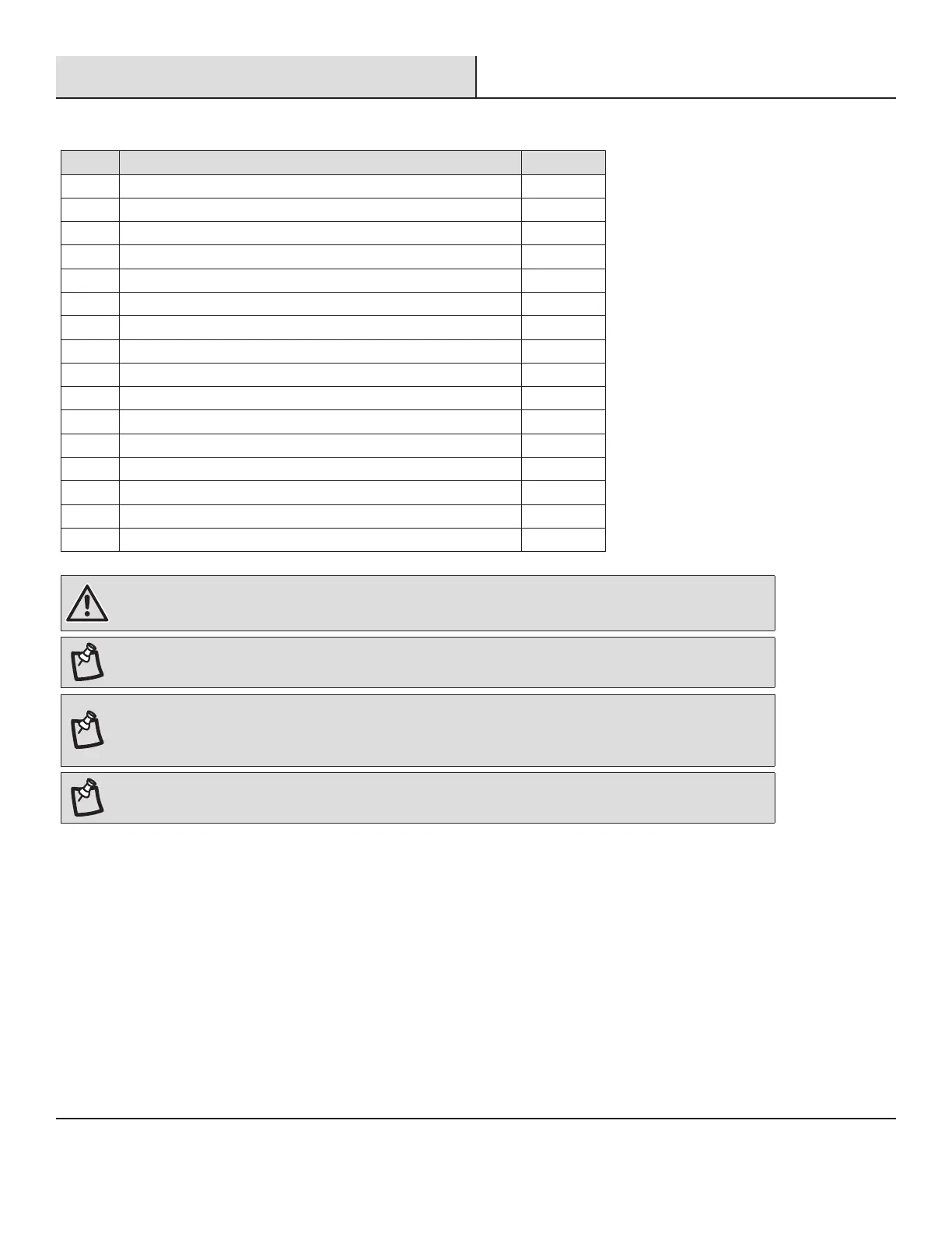
MATERIALS REQUIRED (NOT INCLUDED)
Part Additional items needed Quantity
AA 1-1/4 in. Foot Valve 1
BB 1-1/4 in. Priming Tee 1
CC 1 in. Female PVC Adaptor 2
DD 1/2 in. Pressure Relief Valve 1
EE 1-1/4 in. PVC Pipe Schedule 80, or PVC Pipe Schedule 40 as needed
FF 1-1/4 in. Coupling (required if using PVC Pipe) 1
GG 1/2 in. x 1/2 in. Drain Valve 1
HH 4 in. Well Seal 1
II 1-1/4 in. Flexible PVC Coupling (required if using PVC Pipe) 1
JJ 1-1/4 in. Check Valve 1
KK 1 in. Discharge Tee 1
LL 1 in. Male Adaptor 1
MM 10 in. Tank Tee (or recommended size based on tank size) 1
NN 1/4 in. Plug 1
OO 2 in. Pressure Gauge 0-100 Psi 1
PP 1-1/4 in. Male Adaptor 3
WARNING: All joints and connections must be AIRTIGHT. A single leak will prevent the proper operation of the pump.
Wrap thread tape clockwise on all threaded connections. For all non-threaded connections, you must use PVC Purple
Primer and PVC Cement to ensure airtight seals. Measure all pipe lengths before attaching.
NOTE: Either Schedule 40 or 80 pipe will work in this installation. Be sure to check your state and local building codes.
NOTE: A foot valve is a check valve that is used to keep the water from running back into the well from the pump and
maintain hydraulic pressure when the pump is not running. If the foot valve does not hold the water the pump will lose
it’s prime and will not pump water. If the foot valve open pressure is too high (the spring is too stiff), or the flow area is
too small, the pump suction head and flow rate will significantly drop.
NOTE: The suction pipe size should not be less than 1-1/4 in. The suction size of this pump is 1-1/4 in. FNPT.