41
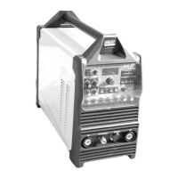
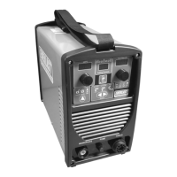
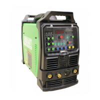
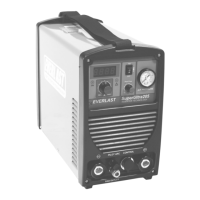
Component Identification and Explanation
settings.
2. Tungsten Size Selector: .040”, 1/16”, 3/32”, 1/8” and Manual. Availa-
ble in all Function modes. “Manual” allows lowest Start Amp settings.
3. TIG Start Type. Includes HF Start, Lift Start with Remote Function, and
Live Lift. When the Spot Weld Function is selected, the TIG start
Type becomes unavailable for selection and HF is set as the default
due to the nature of Spot Welding. Although it is available for selec-
tion in AC mode, “Live Lift” is best used for DC purposes since it
runs a greater risk of Tungsten contamination.
4. Independent Amplitude Status Setting: OFF or ON. For most basic
mode keep setting to “Off” to keep EN (-) and EP(+) Amp value equal
when Welding Amps is adjusted. When “On” is selected, the graph
line and parameter line will expand to include separate settings for EN
(-) and EP (+) Amp values.
5. Pulse Status Setting: Off, Standard AC/DC (on some early models:
ON), and Advanced AC Pulse. Unavailable when the Spot Weld func-
tion is selected.
6. Spot Timer: Off, SPOT ON. When turned on, this function adds both
Spot and Stitch Timer parameters to the graph line. Remote Operation
Setting, Tig Start Type and Pulse functions are not available for selec-
tion when Spot is turned on. By default, these functions are set to
“Off”. Use of the Spot function overrides the Remote function and
defaults to 2T (torch switch use only). Remote will be grayed out.
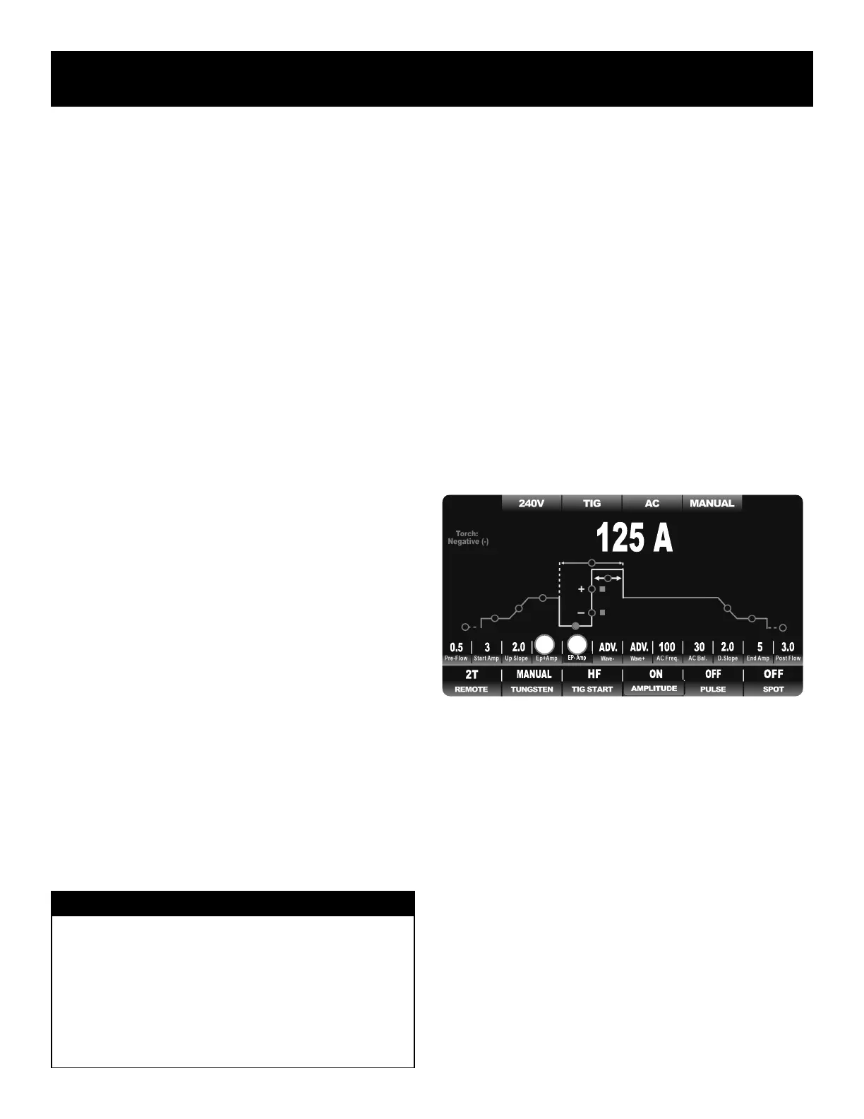
AC TIG FUNCTION WITH INDEPENDENT AMPLITUDE MENU:
• NO PULSE
• WITH PULSE
• NO SPOT
• WITH SPOT
Regardless of the AC function selection, or parameter settings, when In-
dependent Amplitude is selected, the yellow portion of the graph line and
the parameter line changes and expands to add Independent Electrode
Positive (EP+) and Independent Electrode Negative (EN-) Amperage pa-
rameters. During standard operation with the pulse turned off, the Welding
Amps sets both EN- and EP+ Amperage. With Independent Amplitude
turned off, both polarity halves of the AC cycle are locked together so that
both are set equal. This is the traditional way Amps are adjusted with most
TIG welders. When Independent Amplitude is turned on, the default loca-
tion of the main welding Amperage is transferred. It is moved from the
previous Welding Amp location on the green graph line over to the EN–
location at the bottom portion of the yellow AC cycle. (See the location of
the red indicator dot below The former Welding Amps location on the
green line becomes EP+. The EN– value is adjusted in Amps while the
EP+ value is adjusted as a percentage of EN– Amperage (ranging from10
to 125% of EN-). The default Amperage adjustment then shifts to EN–
since the EN becomes the new “Welding Amp” setting for both standard,
pulse, and spot weld AC modes.
The sample below demonstrates what the weld graph should look like in
the basic AC mode after Independent Amplitude is turned activated. Even
though the appearance of the AC graph line and list of parameters may
change when Pulse or Spot Weld is turned on, the order, appearance and
function of the AC Amplitude remains the same.
Only the additional related to Independent Amplitude parameters and func-
tions are listed below. The other parameters and functions have been dis-
cussed in the previous section.
Additional Parameters of Independent Amplitude:
1. Electrode Positive Amps: 10-125% of EN-. Replaces Welding Amp
Setting when Independent Amplitude is selected. When selected, it
no longer serves as the default Amp location. It defaults to EN-.
2. Electrode Negative Amps: 120V 3-330A. This becomes the default
location and value for welding Amps and represents the negative half
of the AC cycle. It is also used as the “peak” current value for Pulse
when pulse is selected.
Additional Functions of Independent Amplitude:
There are no additional functions when Independent Amplitude is selected.
AC TIG FUNCTION WITH PULSE MENU:
• NO INDEPENDENT AMPLITUDE
• WITH INDEPENDENT AMPLITUDE
NOTICE:
On early models of the Typhoon series, the location of the Electrode
Negative (EN-) and Electrode Positive (EP+) settings were reversed
from what is shown here. To improve operation flow and to make the
graph more technically correct, the graph line order has been reversed
to show EN- at the bottom of the AC cycle and EP+ at the Welding
Amp location. Regardless, the operation and adjustment instructions
will remain the same for both EN– and EP+. There is no practical dif-
ference in the adjustment procedure or parameter values.
1 2
AC TIG Screen Setup, Functions and Parameters
 Loading...