45
Component Identification and Explanation
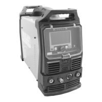
DC TIG Screen Setup, Functions and Parameters
be used together. When the Spot or Fast-Tack function is selected, even
though it is available to select while Pulse is turned on, Pulse is automati-
cally made unavailable and deactivated if Spot ison. When Spot is deac-
tivated, if Pulse was selected, Pulse will be automatically reactivated.
Since the rest of the parameters and functions are not changed, only the
additional and relevant parameters and pulse function are listed below in
logical flow of the weld cycle, from left to right. The Pulse Wave Form
selection is not part of the parameter line, but is rather part of the function
line. When Pulse is rst turned on, this will be the rst adjustment availa-
ble and will be selected as part of the Pulse function. But, if there is no
additional input or selection of wave form within ve seconds, the pro-
gramming will default back to the Welding Amps/Peak Amps location. The
Wave form circle and status can only be changed from the Pulse function
location and will be skipped over in normal adjustment of the other pulse
parameters.
Additional DC Pulse TIG Functions.
1. Welding Amps: 2-330A. This is the default home location of the unit’s
programming. When Pulse is selected, either for Standard AC Pulse
or Adv. AC pulse, this value also represents the “peak” current value
location when a Pulse mode is selected.
2. Pulse Time On: 5-95% of EN-Amps. The Pulse Time-On divides the
time between the Welding Amp Phase (Peak Current) and the Pulse
Amperage phase (Base Current) of the Pulse.
3. Pulse Frequency: : 0-999.9Hz. This represents the number of times
the pulse cycles completely in one second. Pulse Frequency can also
be referred to as “Pulses Per Second.”
4. Pulse Amps/DC Pulse Amps: 3-100% of Welding Amps. When
Standard Pulse Mode is being used, this represents the low Amper-
age value phase (Base Current) of the Pulse.
DC Pulse Function
1. Pulse: Adv. Triangle, Trapezoid and Sine. The Pulse wave form fea-
tures 4 different shapes. When pulse in active, each wave form offers
a different depth of control of the pulse and imparts a distinctive,
nuanced feel and weld characteristic. The Pulse wave shape indicator
is located on the weld graph line with the parameters, even though
the control is located on the Function line.
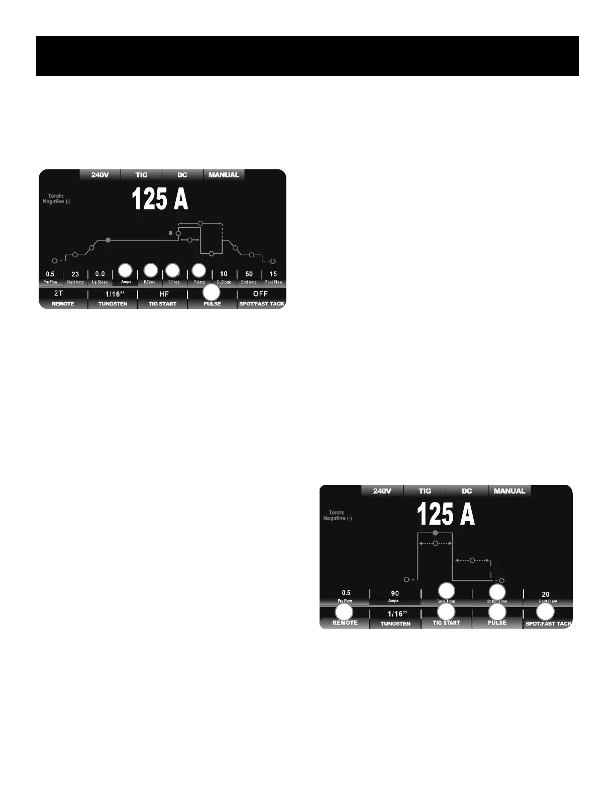
DC SPOT/ FAST-TACK MENU:
• NO PULSE AVAILABLE
• MUST USE WITH 2T TORCH SWITCH OR TRIGGER
• HF DEFAULT START ONLY
The DC Spot Weld/ Fast-Tack menu and graph line is greatly simplied
and contracted in size due to the nature of a spot weld. Typically a spot
weld is a brief, but intense arc of Amperage with a rapid termination. A
Fast-Tack weld is similar but has a much more short duration. These two
types of welding eliminate the need of many parameters and functions. The
Start Amperage, End Amperage, Up Slope and Down Slope parameters are
eliminated from the menu screen completely. The appearance and func-
tion of both the Spot Weld setting and the Fast Tack Setting are identical,
with the exception of the time unit values. Spot Weld is in .1 second incre-
ments. Fast-Tack time setting value is in milliseconds with a minimum of
10 ms. Functions which are defaulted to a required setting for Spot Weld-
ing and Fast-Tack are grayed-out and labeled with an “N/A” (Not Available)
status. As a result, the menu is locked into the 2T mode and HF Start
mode. The torch switch should be used with this function for proper oper-
ation. The Spot Weld setting is a longer version of the Fast-Tack Version
and is used for areas where small spot welds and seams are needed. The
Fast-Tack is designed for welding of extremely thin metal with extremely
quick, successive on/off bursts of relatively high Amperage. The Fast-Tack
is also called “Cold Welding” even though it may use relatively high Am-
perage in each burst.
The additional and relevant parameters related to Spot Welding/ Fast-Tack
Welding are listed below. Also, Spot/Fast-Tack functions that have a spe-
cial status when the Spot Weld function is used are listed as well.
Additional DC Spot/ Fast-Tack Weld Parameters.
1. Spot Timer, Fast-Tack Timer: For Spot .1-10S; For Fast Tack 10-
250ms. The Spot weld timer duration can be programmed down
to .1 seconds. The Fast-Tack, (cold-weld) timer can be programmed
down to 10 milliseconds, or .01 Seconds. This is the “Arc On” time.
2
3 1
F1
4
2
1
F2
F1 F3
F4
 Loading...