189
FUEL SYSTEM
FUEL COMPONENT SERVICING
8
supplied with all replacement injectors on 3.5 in.
floppy disk.
The following items and their mating surfaces
must be cleaned before reassembly:
• Injector
• Cylinder head
• Adapter
• Screws
• Threaded areas
Place injector and insulator in the proper cylinder
location.
IMPORTANT: Be careful not to pinch any wiring
or hoses during assembly.
Lubricate mounting screw threads and under the
head of the screw with a light coat of Triple-Guard
grease. Install washers (one per screw) on injec-
tor retaining screws. Install screws and washers
through mounting flange of injector and thread
into cylinder head.
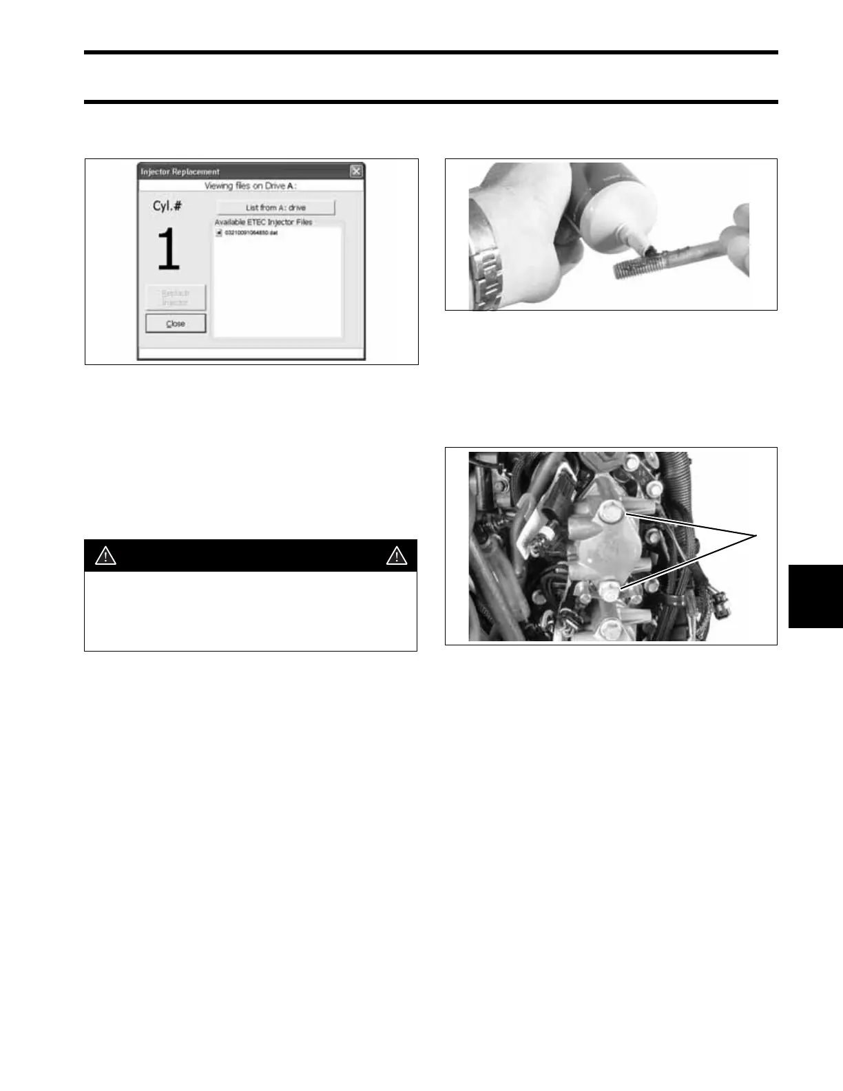
Tighten screws in stages, starting with the lower
screw.
• First torque is 5 ft. lbs. (7 N·m)
• Second torque is 10 ft. lbs. (14 N·m)
• Final torque is 24 to 26 ft. lbs. (33 to 35 N·m).
Reconnect fuel injector/coil electrical connectors.
If ignition coil lead was removed from connector,
refer to CONNECTOR SERVICING on p. 164.
Install fuel manifolds. Refer to Fuel Manifold Ser-
vice on p. 186.
IMPORTANT: Install injector service data (3.5
in. floppy disk) by using the Injector Replacement
Utility of Evinrude Diagnostics software. Check
the Injector Coefficients screen to make sure that
all injectors are positioned properly.
004160
CAUTION
All injector components must be clean to
ensure correct torque tightening specifi-
cations. To prevent fuel leakage, carefully
follow these installation instructions.
002316
Tighten Screws in Stages
1. Screws
005338
1