32
INSTALLATION AND PREDELIVERY
BOAT RIGGING
Battery Switch Operation
• Select the primary battery for normal operation.
• Secondary batteries should only be selected for
emergency starting.
• ALL or BOTH switch position is for emergency
starting only.
Provide operator with the documentation sup-
plied by the battery switch manufacturer. Make
sure that the operator is informed of proper
battery switch operation.
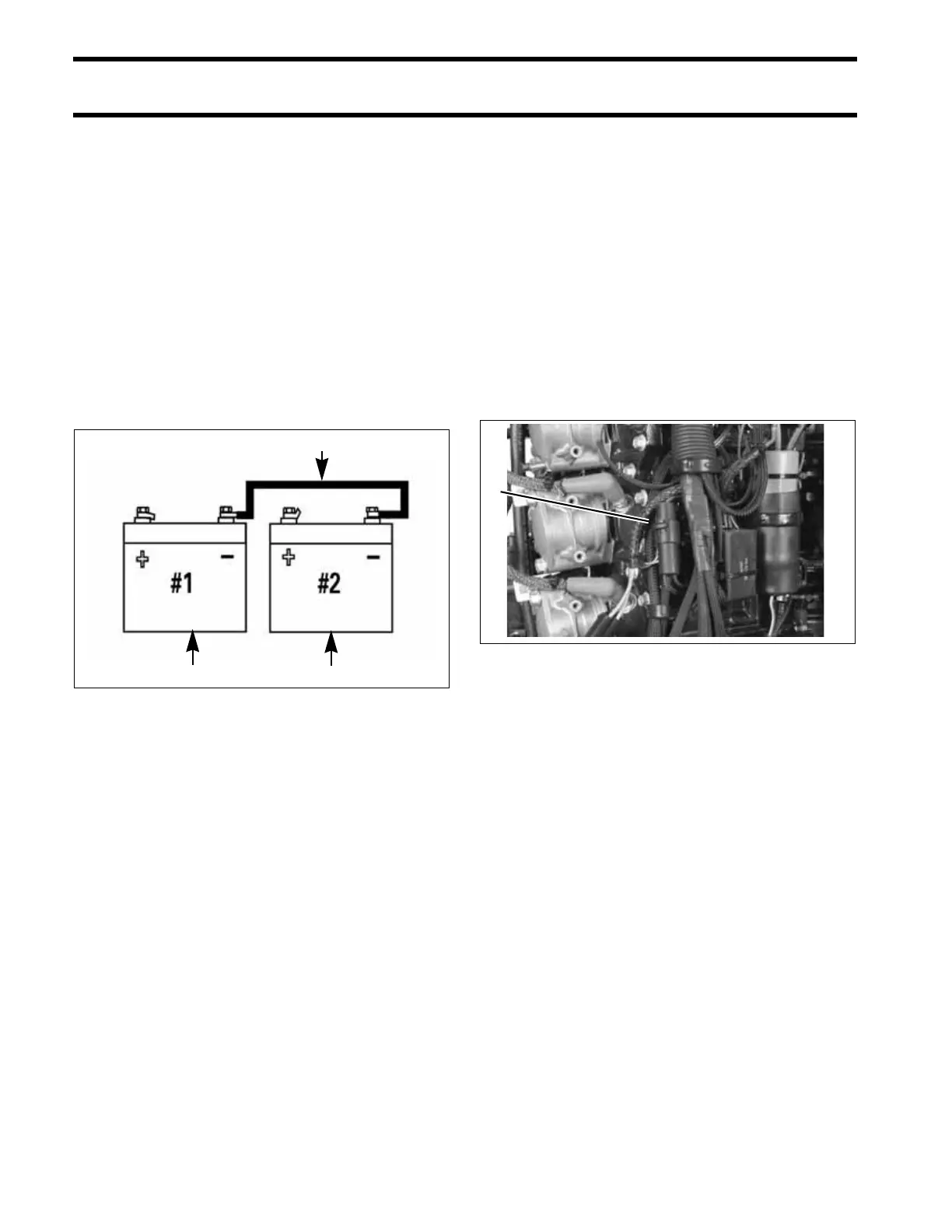
IMPORTANT: The negative (–) terminals of a
multiple 12-volt battery installation must be con-
nected together.
Auxiliary Battery Charging
Evinrude E-TEC V4–V6 outboards are equipped
with isolated battery charging capability. The iso-
lated charge connection must only be used to
charge a single 12-volt battery or two 12-volt bat-
teries wired in parallel.
IMPORTANT: Never connect an external bat-
tery isolator to the stator of an Evinrude E-TEC
outboard.
Accessory Charge Lead Kit, P/N 5006253, is
routed from a connector on the outboard’s electri-
cal harness to the accessory battery.
IMPORTANT: The accessory charging kit must
never be connected to any battery of a 24-volt
electrical system.
1. Starting battery (primary)
2. Accessory battery (secondary)
3. Cable connecting negative (–) battery terminals
DRC7284
1 2
3
1. Accessory battery charge connector 004944
1