19
6.0 Installation and initial operational set-up
NOTICE
Damage due to penetrating liquids
Liquids which get on the guide tube can damage the pillar.
Therefore:
• Locate the appliance so that the device will not be exposed to liq-
uids.
• Align the pillar during installation (⮑ g. 9) so that liquid which
gets in the guide tube cannot get into the inner guide tube.
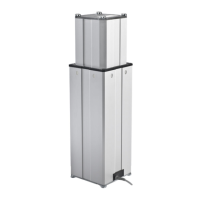
1. Loosen and remove the four transport screws at the top (1).
Fig. 11
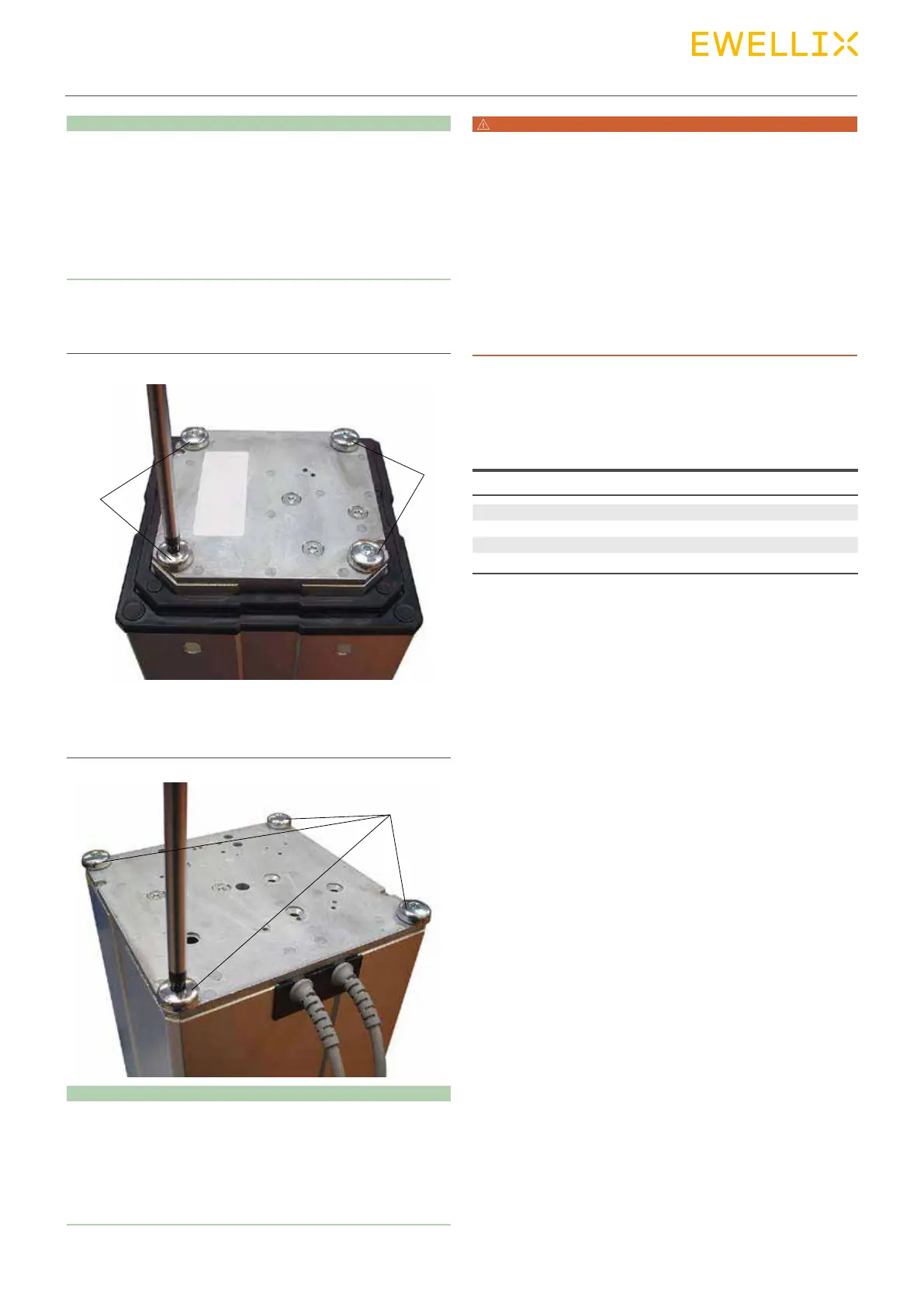
2. Loosen and remove 2 the four transport screws at the
bottom (2).
Fig. 12
NOTICE
Malfunctions due to scratching!
Scratching the side surfaces of the tubes can lead to malfunctions
during operation.
Therefore:
• During installation, ensure that the tube side surfaces are not
scratched.
1
1
2
WARNING
Risk of injury and property damage due to insufficient
fastening!
Inadequate attachment can cause the base plates (3) and (6) to
break and lead to serious injuries or damage.
Therefore:
• Useonlythespeciedscrewsformounting.
• When using attachment plates supplied by the customer, ensure
that the base plates are always supported completely and the
force is borne by the entire surface.
• Ensure that the steel or aluminum attachment plates supplied by
the customer are at least 10 mm thick.
3. Attach the lower attachment plate (4) with four screws (5)
on the outer guide tube or the lower base plate (6) using
thespecicationsbelow.
Use the following screws for mounting:
Type THG TLG/TLT
Screws (1), (5) M6 (4 pc.x 2) M10 (4 pc.x 2)
Minimum screw-in depth 22 mm 25 mm
Strength category 10,9 10,9
Tightening torque 9 Nm 40 Nm