20
THG/TLG/TLT
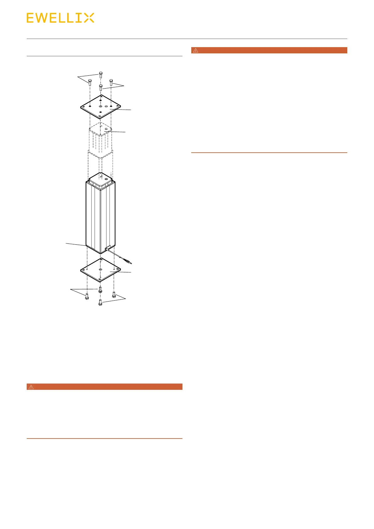
Fig. 13
Attaching the telescopic pillar
4. Ensure that the minimum screw-in depth and screw
tightening torques are complied with (see above table).
5. Attach the upper attachment plate (2) with four screws (1)
on the inner guide tube.
6. Ensure that the minimum screw-in and screw tightening
torques are complied with (see above table).
7. Connect attachment plate (4) and (2) and elements of the
application with attachment screws.
WARNING
Risk of injury and material damage due to excessive load!
Overloading the pillar can destroy the device which can lead to
serious injuries or property damage.
Therefore:
• With excentric loads, take note of the load diagram (⮑ technical
data sheets in the appendix) or contact the manufacturer.
WARNING
Risk of injury from moving parts!
While driving onto solid objects, the force of the device may cause
injuries. In the retracted end position, there is a risk of crushing
between parts of the pillar.
Therefore:
• When retracting, ensure that no objects or body parts can be
caught between the attachment plate (1) of the inner tube and the
outer tube (2).
• When retracting, ensure that no objects or body parts can be
caught between the attachment plates (1) and (3).
• If there is a risk of injury, depending on the installation location, a
mechanical safety device must be installed.
8. Ensure that the telescopic pillar is not hindered in its
movement anywhere in the lift area. Consider collision
tests of the application.
9. When retracting, ensure that no objects or body parts
can be caught between the attachment plate (1) of the in-
ner tube and the outer tube (2) (⮑ g. 13).
10. Ensure that the motor cable cannot be crushed, pinched
or pulled.
11. Ensure that the operating cable cannot be crushed,
pinchedorpulled.Thereisnolocationdenedfor
mounting support the operating element. Ensure that the
buttons on operating element cannot pressed without in-
tention.
12. Connect the telescopic pillar to the control (refer to chap-
ter ⮑ 6.3 Inspection prior to rst operation).
13. Connect the operating element to the control (refer to
⮑ Separate operating manual).
1
1
2
3
6
4
5
5