41
11.0 Appendix
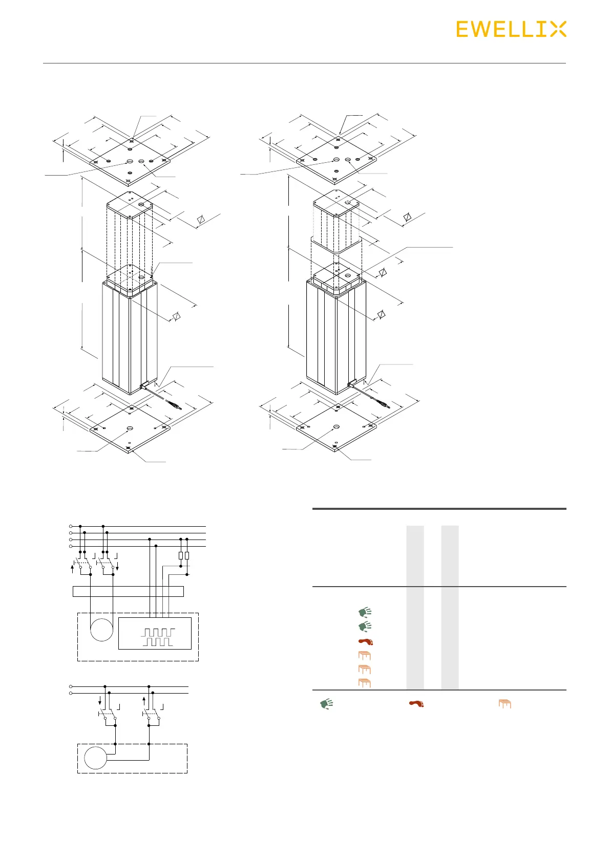
Dimensional drawing
Connecting diagrams Suitable control units and accessories
Note: mounting plates are not
included.
To be ordered separately.
Legend:
S = stroke
L = retracted length
220
190
101
15
Ø22
Ø11
200
170
101
Ø20
25
25
129
146
4 x M10/30
40 Nm
4 x M10/30
40 Nm
220
190
129
15
200
170
129
Ø11
Ø22
Ø11
Ø22
Stroke ±2
Retracted
length ±2
220
190
101
Ø22
Ø11
200
170
101
Ø20
25
25
129
146
163
4 x M10/30
40 Nm
4 x M10/30
40 Nm
220
190
146
15
200
170
146
15
Stroke ±2
Retracted
length ±2
1)
Only valid with TLG11. TLG10 must be operated by a
BCU, MCU, SCU or VCU control unit.
DIN Plug - 24 V DC
+
-
M
5V+
GND
1+7
2+4 3 5 6 8
DIN8 plug
Blue
2 Hallsensors signal
Actuator
Red
+
-
M
Black
Actuator
Red
Jack Plug - 24 V DC
1,5K 1,5K
Hall A
Hall B
Control units
SCU
VCU
BCU
MCU
TLG
� � � �
Operating switches
EHA 1
�
EHA 3
� � �
STF
�
STJ
� � �
STA
�
STE
� � �
Desk switchHand switch Foot switch