AvediaStream e2535/e3635 and e2655/e3655 Encoders V1.1
12 Administrator’s Guide
2 Physical Interfaces
AvediaStream e26xx and e36xx encoders can operate in any of the following chassis:
● AvediaStream c1101
● AvediaStream c1103
● AvediaStream c1110
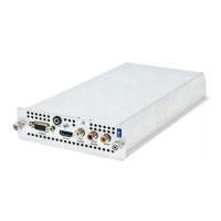
The encoder has AV interfaces on its rear panel, while its edge connector enables it to access
network and admin ports via the chassis front panel.
Caution: Take care not to touch the edge connector as static electricity might damage the
product. Handle by the enclosure only and insert as soon as possible into the chassis.
Chassis Interface
The Encoder module provides the following interfaces over its edge connector to the chassis:
● Ethernet interface (10/100Mbps)
● Admin Interface
● Status LEDs
● Power supply
The actual physical interfaces can be found on the chassis front panel. Please refer to the
relevant AvediaStream Installation Guide for further details.
Heartbeat LED
The heartbeat LED (marked H/B) on the AvediaStream front panel provides an indication of
the current state of the unit without using any of the management interfaces. The LED
behaviour is described in Table 2 Heartbeat LED Patterns.
Table 2 Heartbeat LED Patterns
Running Power on Self Tests
Booting operating System, takes
approximately 10-20 seconds
Heartbeat indicates unit is running normally
Alternatively < 1 sec, > 10 secs