Remote modules. RIO5, RIOW and RIOR series.
CNCelite
8058 8060
8065 8070
5.
RIOR-E-48I32O / RIOR-E-48I32O-ANALOG (CANOPEN).
Description of connectors.
ꞏ94ꞏ
REF. 2107
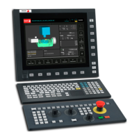
ꞏD46ꞏ ERR led, transmission status indicator.
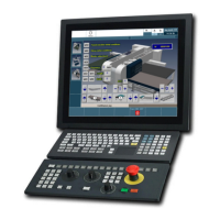
ꞏI44Aꞏ/ꞏI44Bꞏ Digital inputs and outputs.
See "5.6 Connection of the digital inputs and outputs." on page 98.
Red LED. Its meaning depends on the blinking speed.
Blinking rate. Description.
Off. The module is ready to run.
Intermittent. Module configuration stage.
Single blinking. Poor transmission. At least one of the error
counters of the CAN controller has reached the
alarm level.
Double blinking. There is no communication with the cpu.
On Error. The CAN controller is in "Bus Off" state.
D46
D45
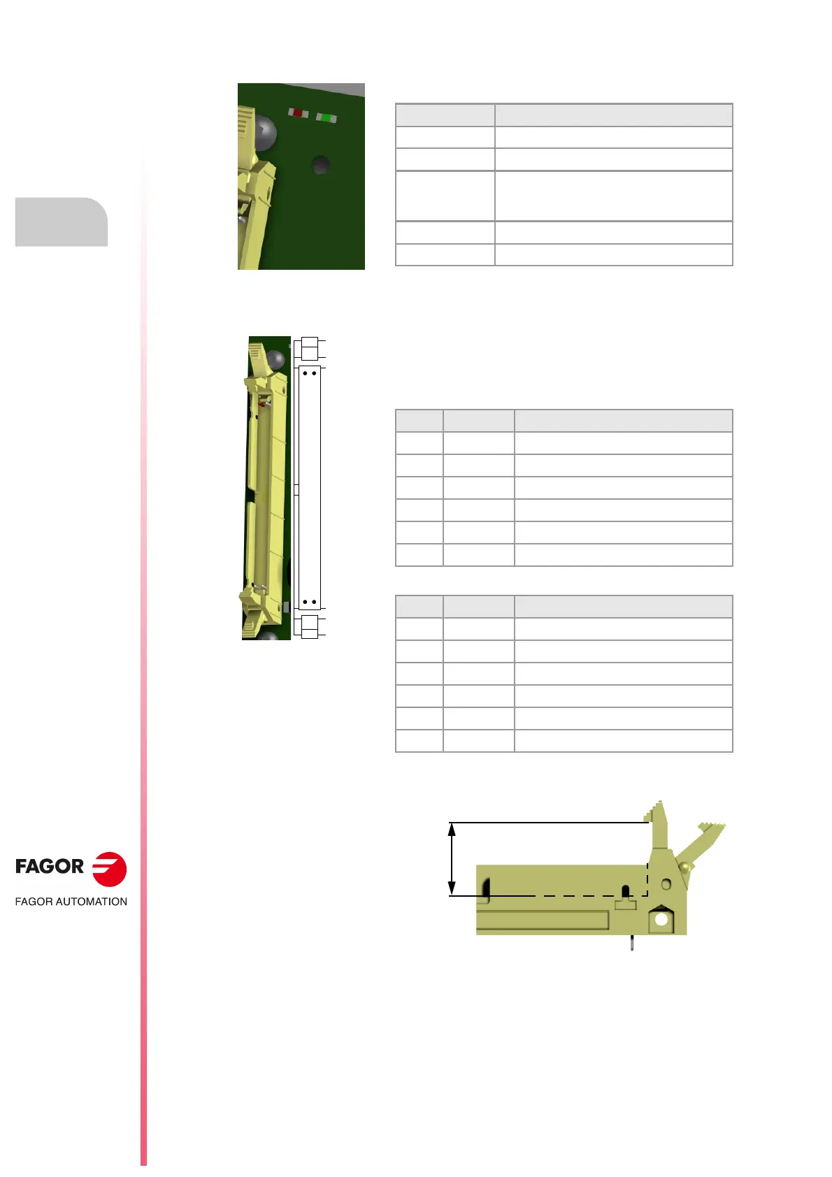
50-pin male IDC connector with a latch. Use a female
connector for ribbon cable. Maximum height of the connector,
14.5 mm.
• Connector ꞏI44Aꞏ.
• Connector ꞏI44Bꞏ.
Pin. Signal. Description.
1 GND 0 V reference signal.
2 24V_OUT 24 V output for digital inputs.
3ꞏꞏꞏ26 I1 - I24 Digital inputs.
27ꞏꞏꞏ30 - - -
31ꞏꞏꞏ46 O1 - O16 Digital outputs.
47ꞏꞏꞏ50 24V 24 V supply for digital outputs.
Pin. Signal. Description.
1 GND 0 V reference signal.
2 24V_OUT 24 V output for digital inputs.
3ꞏꞏꞏ26 I25 - I48 Digital inputs.
27ꞏꞏꞏ30 - - -
31ꞏꞏꞏ46 O17 - O32 Digital outputs.
47ꞏꞏꞏ50 24V 24 V supply for digital outputs.
 Loading...