4. Maintenance
USE AND MAINTENANCE MANUAL CHAPTER 4
MAINTENANCEXEF 250 - Rev01 / 2020
69
4
A
3 2 1
3
A
A
2
1
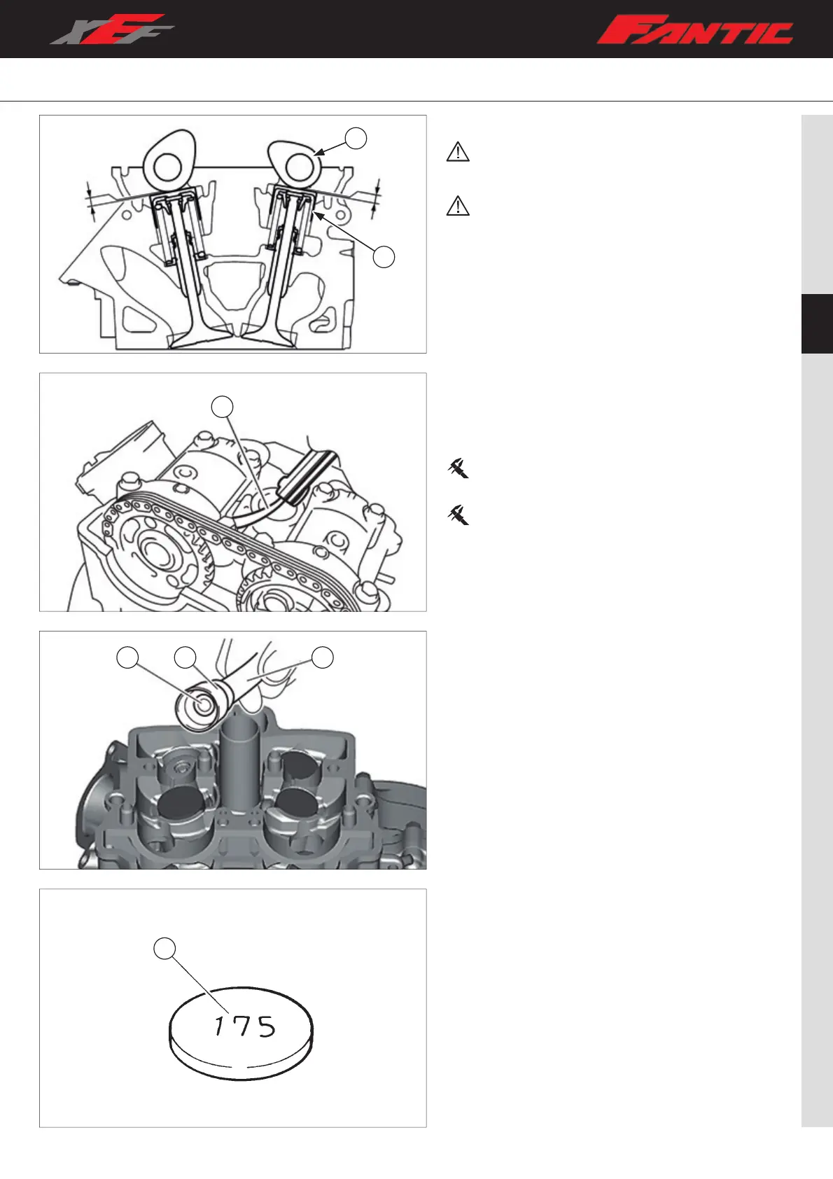
4.5 VALVE CLEARANCE
Make sure that the valve clearance is controlled
and/or adjusted when the engine is cold (ambient
temperature).
While the valve clearance is checked and/or adjusted,
ensure that the piston remains at the top dead centre
(TDC).
Check
– Remove: Seat, left and right conveyors, air filter casing, fuel
tank;
– Remove spark plug and valve cover;
– Perform the engine timing operation (refer to chapter ““4.4
Camshafts” on page 65).
– Measure the valve clearance “A” between the camshaft
lobes “1” and the valve lifters “2”, using a thickness gauge
“3”.
– If the clearance value of one or more valves is not within
the standard values, proceed with the adjustment.
Intake valve clearance :
0.12 - 0.19mm (0.0047 – 0.0075 in)
Exhaust valve clearance :
0.17 – 0.24mm (0.0067 – 0.0094 in)
Adjustment
– Check that the crankshaft and camshaft references are
correctly aligned with the references on the left crankcase
cover and cylinder head;
– Remove the camshafts (refer to chapter “4.4 Camshafts”
on page 65);
– Remove the valve lift “2” and the adjustment plate “3”,
relative to the valve to be adjusted, using a magnet “1”.
– Check the thickness of the adjustment plate by checking
the value “A” on the upper wall of the plate. If the value “A”
cannot be read, measure the thickness of the plate with a
micrometer.
– Choose the thickness of the new plate to be installed
according to the following formula:
A=(B-C) + D
A. New plate thickness;
B. Valve clearance detected;
C. Valve clearance specified;
D. Old plate thickness.
 Loading...