Machine description
4812158701_G.pdf2019-10-01
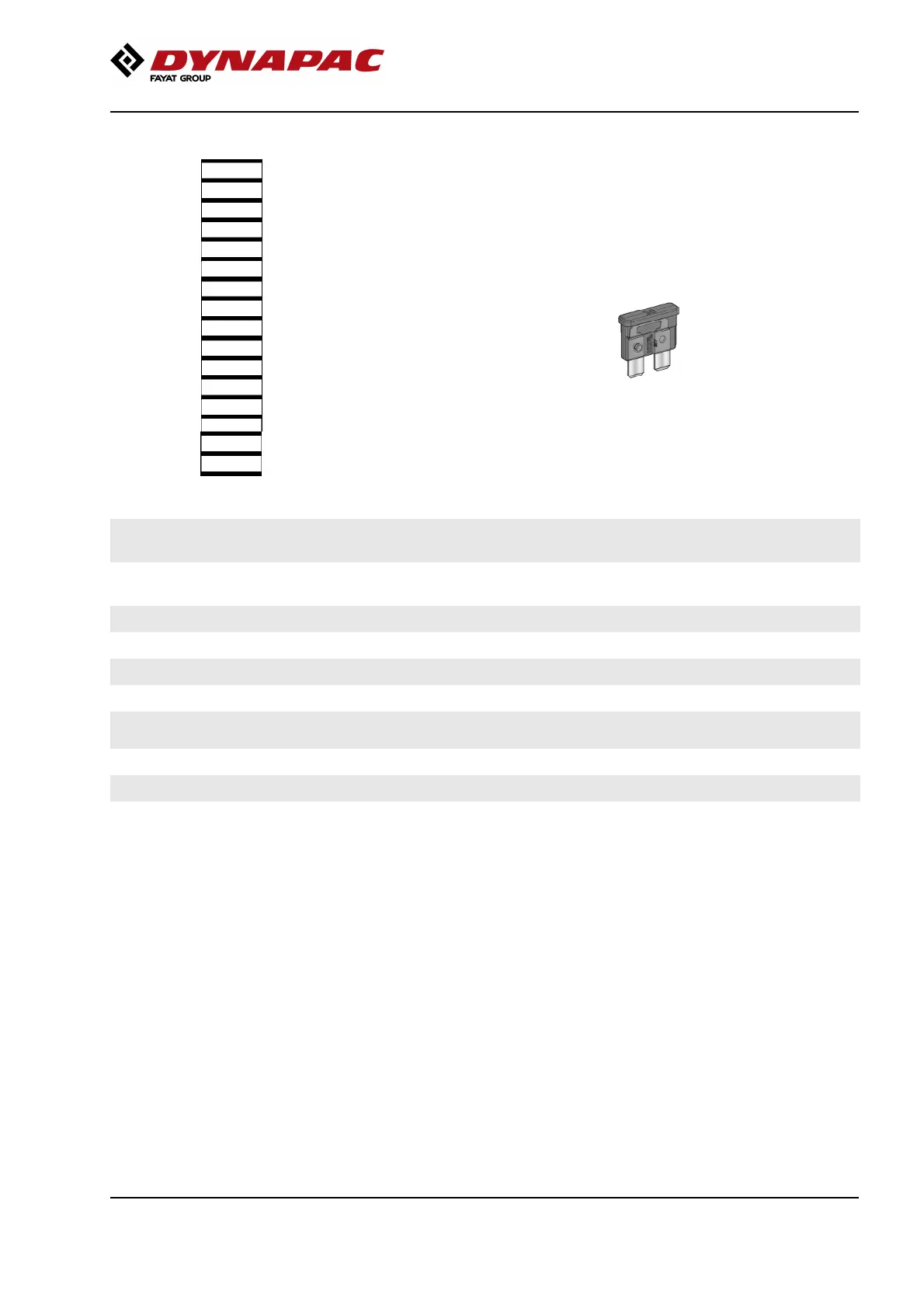
Fuses in the main switchbox (Deutz)
Fig. Fuses
1
2
3
4
5
6
7
8
9
10
11
12
13
14
15
16
The figure shows the position of the fuses.
The table below gives fuse amperage and function. All
fuses are flat pin fuses.
1. Main relay, 24V outlet engine
compartment
10A 9.
*
**
Glow plug relay
NOX sensor
7,5A
15A
1. Main relay, 24V outlet engine
compartment
10A 9.
*
**
Glow plug relay
NOX sensor
7,5A
15A
2. ECU, Outlet boot loading, I/O board,
display
5A 10.
*
**
Reserve
Diesel engine 10A
2. ECU, Outlet boot loading, I/O board,
display
5A 10.
*
**
Reserve
Diesel engine 10A
3. ECU PWR1, Speed/Frequency sensor 10A 11. 12V outlet, Radio/CD 10A3. ECU PWR1, Speed/Frequency sensor 10A 11. 12V outlet, Radio/CD 10A
4. ECU PWR2, Forward/Reverse lever 10A 12. GPS, DCM, DCO, tilt sensor 10A4. ECU PWR2, Forward/Reverse lever 10A 12. GPS, DCM, DCO, tilt sensor 10A
5. ECU PWR 3 20A 13. Reserve5. ECU PWR 3 20A 13. Reserve
6. ECU PWR 4 20A 14. DCA 10A6. ECU PWR 4 20A 14. DCA 10A
7. 24V outlet operator's station,
Tachograph
10A 15. Indicator relay 7.5A7. 24V outlet operator's station,
Tachograph
10A 15. Indicator relay 7.5A
8. Hydraulic/Fuel sensor, Engine 10A 16. Driving lights 10A8. Hydraulic/Fuel sensor, Engine 10A 16. Driving lights 10A
*
(IIIA/T3)
*
(IIIA/T3)
**
(IIIB/T4i)
**
(IIIB/T4i)
55