INSTALLATION MT86/MT86HT Flow Meter
8 Fluid Components International LLC
Input Power
Warning:
The output terminals are not power isolated with use of 24 VDC as a power source.
Note:
Before inserting the cable core into the terminal strip connector, first turn the terminal screws 10
turns counterclockwise. If this is not done, there is a possibility of inserting the wires between the
top half of the clamps and the frames instead of between the two clamp segments.
FCI strongly recommends installing an AC line disconnect switch (and possibly a fuse) between the power source and the flow meter. The
line switch is an easy way to remove power for calibration and maintenance procedures. Also the line switch is an added safety feature.
100 VAC, 115 VAC, 230 VAC or 24 VDC is the power source for the flow meter (use only one power source). Wire the power directly to the
power supply terminal strip TS1.
Isolated Output Option and 4-20 mA Adjustment
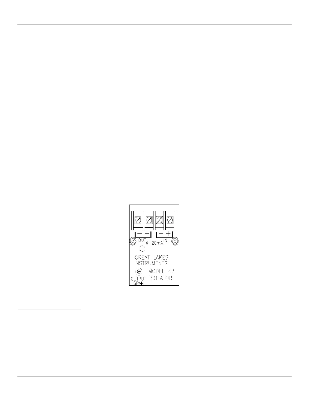
An isolated 4 to 20 milliampere (mA) output is an available option. The isolated output is available by connecting a loop powered isolator
module to the transmitter output. Figure 5 shows the isolator output module. The module has its own set of output terminals which provide
an isolated 4 to 20mA output equal to the non-isolated instrument output. This one-to-one current isolation is used to prevent
instrumentation ground loops. See Figure 3 or Figure 4, page 7, for the appropriate wiring diagram to install the isolated output module.
Use of the isolator module will add a small signal conversion error to the instrument output and limit the output load to 350 ohms. The
module must be adjusted in the field to the specific customer load. A red LED on the module indicates when loop power is applied.
1. Connect the customer load with a milliampere meter in series with the output terminals of the isolators.
2. Connect a milliampere meter in series with the input terminals.
3. Apply power to the instrument. Initiate a full process media flow. Allow a 10 minute warm-up period.
4. Adjust the isolator output span potentiometer (see Figure 5 below for placement) so both of the milliampere meters read the same.
5. This completes the output isolator setup. Turn off the power, remove the milliampere meters and reconnect the wiring.
Figure 5 –Isolator Output Module
Installation Quick-Check List
1. Verify that serial numbers match.
2. Properly orient the flat and flow arrow.
3. Ensure there are no leaks at the process connection.
4. Verify that the wiring is properly connected per the wiring diagram.