MT86/MT86HT Flow Meter GENERAL
Fluid Components International LLC 1
1 GENERAL
Description
The MT86 and MT86HT is an air and gas mass multipoint flow meter that incorporates one or more flow elements connected to a flow
transmitter. Together they are designed to measure the mass flow in pipes, ducts or stacks. The flow meter accurately measures the
irregular flow profiles. An MT86 or MT86HT measures flow from up to eight individual sensing points. An average of the individual flow
signals gives an output signal that represents the total mass flow. This output signal operates up to four different output modules of choice.
Operating Principles
The flow meter has flow elements containing sensing points that are connected to the flow transmitter (control circuit boards) by a wiring
harness. The flow elements and the flow transmitter are usually separated by some distance that in some cases can be up to 1000 feet
(300m). The output that comes from the flow transmitter goes to the customer's applications, such as valve control circuitry, alarms or
meters. The operational theory of the flow element sensing points and the flow transmitter are discussed below.
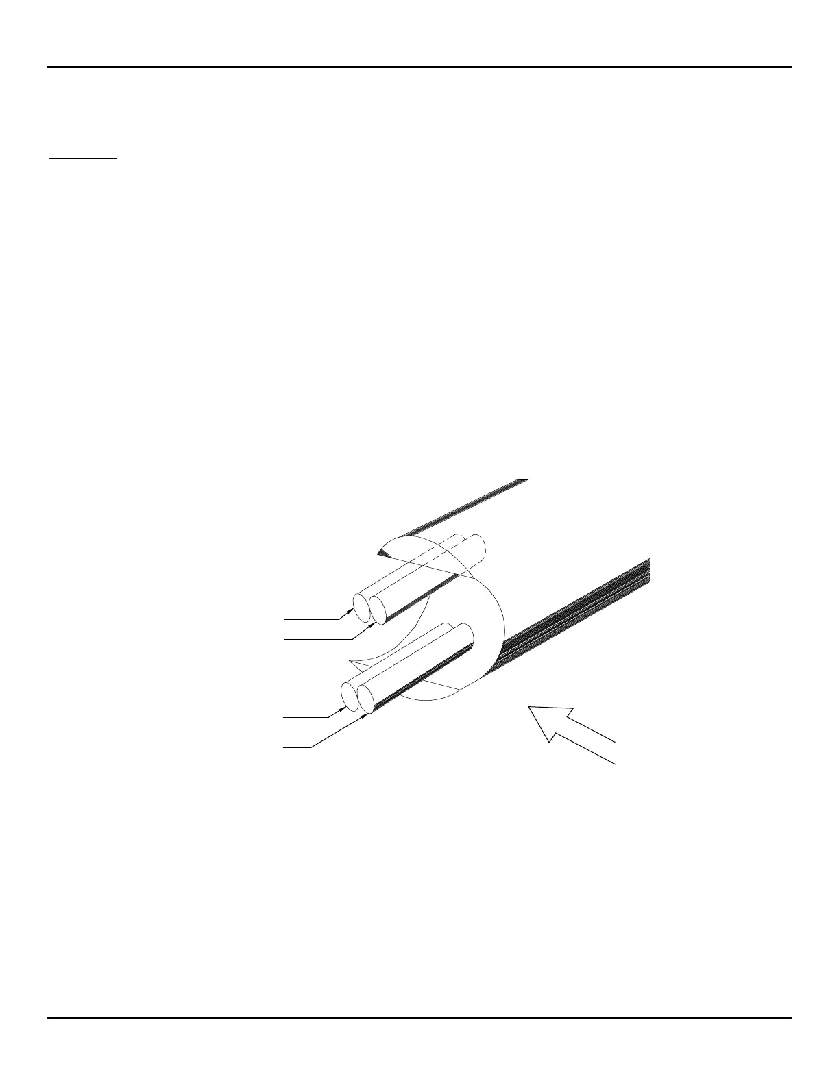
Flow Element
The flow element consists of 2 to 8 sensing points. Each sensing point has two pairs of thermowells (metal tubes) of the same size and
shape. Each pair of thermowells is welded together. One thermowell pair has a heating element placed in one tube and an active
Resistance Thermal Detector (RTD) placed in the other tube. The other thermowell pair has a reference RTD placed in one tube and an
empty thermowell tube that is for mass equalization. See Figure 1 for a cut away view of one sensing point.
The two pairs of thermowells are physically separated by a distance that allows the process media to flow between them and yet prevents
thermal interaction between the two pair, see Figure 1 below.
Figure 1 –Cut-Away View of One Sensing Point
Flow Transmitter
Each sensing point is connected to a separate flow transmitter circuit. The basic functions of the flow transmitter are to provide power to
the flow element, measure the temperature differential (∆T) between the two RTDs as a function of resistance, amplify and linearize the
resistance differential (∆R) measurement of the flow element input signal and to provide an output signal. The linearized signals from the
sensing points are then averaged together and converted into the final output signal (4-20 mA, 0-5 VDC, 0-10 VDC, etc.) as specified by
the customer.
The flow transmitter has a diagnostic alarm. If a problem exists with a sensing point, a Light-Emitting-Diode (LED) on the control board
flashes to notify the customer.
REFERENCE RTD
MASS EQUALIZING
HEATER
ACTIVE RTD
C00124-1-2
TUBE
F
L
O
W