MT86/MT86HT Flow Meter TROUBLESHOOTING
Fluid Components International LLC 31
6. If the flow meter has a local display and the new EPROM changes the calibration range, then the display will need to be re-spanned to
the new range.
7. Turn the operating power ON, and then allow five minutes for the flow meter to stabilize.
8. Make a new Delta "R" data sheet for each flow element when the flow meter is operating correctly. The new sheets will be useful when
future calibration and verification checks are made.
General Circuit Board Replacement Procedure
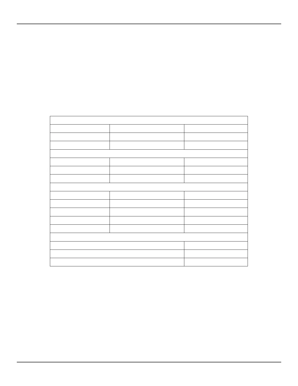
For matching equipment, 100 ohm or 1000 ohm, see Table 10. Table 10 covers the control board and input boards. The power supply,
output board, and display are interchangeable regardless of flow meter type.
The control board is interchangeable for same type call-out. In other words, a control board for a 1000 ohm sensing element is
interchangeable with another control board for a 1000 ohm sensing element, adjustments may be needed.
Table 10 - Components for 100 and 1000 Ohm Flow Meters
R8 4.99K, 1% 21.5K, 1%
Gain 20X 10X
Jumpers Installed, Input Board
J1, 2, 4, 6, 7, 8, 10, 12
002 N/A J1, 2, 4, 6
003 J3, 5, 9, 11 N/A
004 J3, 5 N/A
Jumpers Installed, Output Board
Input Board Replacement Procedure
Spare input boards MUST be factory pre-adjusted for the specific flow meter and flow element sensing points. See Figure 14 for the PWB
parts placement.
1. Turn the operating power OFF.
2. Disconnect the flow element cable from the input board.
3. Remove the four hold-down screws from the input board being replaced. Grasp the PWB and lift while gently rocking the board from
side to side.
4. Position new PWB in the same orientation as the old PWB. Gently press down over the connector to seat it.
5. Install the four hold-down screws in the new PWB.
6. Reconnect the flow element cables to the PWB. Remove the "HTR+" and "HTR-" wires from the connectors and continue with the next
procedure.
7. Perform a sensing point balancing procedure. Contact FCI customer service for the appropriate procedure.